


Communication Manager Maintenance-Object Repair Procedures
984 Maintenance Procedures for Avaya Communication Manager 3.0, Media Gateways and Servers
If the circuit pack has an entry in the circuit plan and either of the other two conditions are
not met, a MINOR alarm is logged. To resolve the error, either:
● Make sure all conditions for administration are met and that a functioning DS1 circuit
pack is inserted in the correct slot, or
● Completely remove the DS1-BD from the system:
1. Remove any administered DS1 trunks or access endpoints associated with the circuit
pack from their trunk groups.
2. Execute remove ds1 location and change circuit-packs UU.
If all the administration conditions are met for this circuit pack and the red LED is still on,
follow the instructions in LED alarms without Alarm Log entry or with Error Type 1
on
page 258.
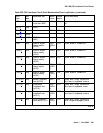
c. Error Type 18: the DS1 Interface circuit pack has been busied out by busyout board
location.
d. Error Type 23: the DS1-BD circuit pack is not completely administered. Ensure that the
DS1-BD circuit pack has an entry in the circuit plan via change circuit-packs, is
administered via add ds1 location, and is inserted into the correct port slot.
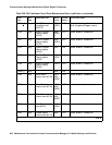
e. Error Type 125: the circuit pack in the slot does not match the type administered to that
position. Either replace the circuit pack with one of the type administered, or use change
circuit-packs to re-administer the slot. This error may also indicate that the 24/
32-channel selection on the DS1 administration screen does not match the configuration of
the circuit pack.
f. Error Type 257 is associated with the Common Port circuit pack maintenance test. See
XXX-BD (Common Port Circuit Pack/Media Module)
on page 2539 for details.
g. Error Type 513: The DS1 Interface circuit pack has detected a transient hardware problem
(for example, external RAM failure, internal RAM failure, internal ROM failure, or instruction
set failure). This error disappears when no faults are detected for 30 minutes. The value in
the Aux Data field indicates the type of hardware problem. However, when this error is
reported with Aux Data of 4352 to 4358, the circuit pack has reported a hardware failure.
Escalate the problem.
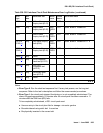
h. Error Type 769: The DS1 Interface circuit pack detected a transient hardware logic error
(for example, program logic inconsistency). This error disappears when no faults are
detected for 100 minutes. The value in Aux Data field indicates the type of hardware
problem.
i. Error Type 1025: CSU module or T1 sync splitter missing. The Near-End CSU Type field
on the add ds1 screen has been administered as integrated, but the 120A1 CSU or T1
sync splitter is not physically connected (or is improperly connected) to the TN767E board
on the back of the port carrier.
If using the 120A1 CSU or T1 sync splitter, plug (or replug) the CSU or T1 sync splitter into
the TN767E circuit pack’s connector on the I/O connector panel on back of the carrier.