Communication Manager Maintenance-Object Repair Procedures
2162 Maintenance Procedures for Avaya Communication Manager 3.0, Media Gateways and Servers
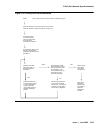
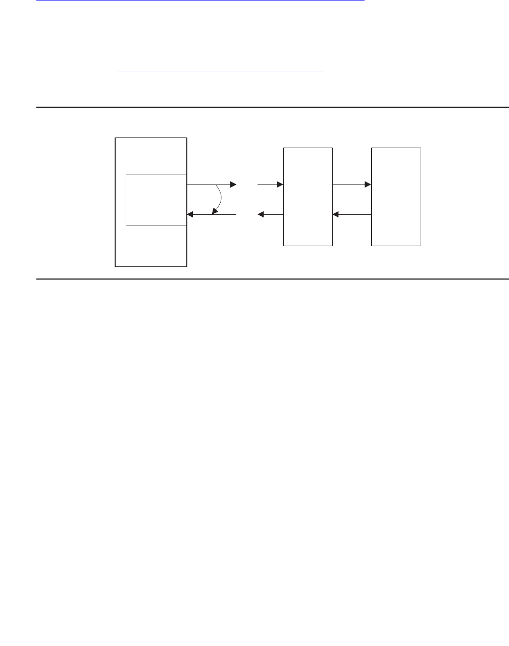
Figure 134: Manual Loop-Around for Facility Fault Sectionalization on page 2162 shows a
sequence of units (1 though n) that may be connected as the on-site equipment. A typical
example is the case where the only on-site equipment is channel-terminating equipment
designated Unit #1. A more complex, less typical example might have a DACS as Unit #1, a
protection switch as Unit #2, and a DS1-level microwave radio system as Unit #3.
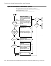
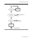
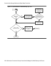
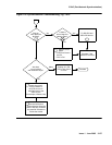
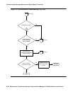
The flowchart in Figure 135: Facility Fault Sectionalization
on page 2163 gives an overview of
the facility fault sectionalization technique. It is important that you know the configuration and
wiring of the equipment for the problem facility in order to support this technique.
Figure 134: Manual Loop-Around for Facility Fault Sectionalization
Since the technique is time consuming, fix any DS1-BD, UDS1-BD, STRAT-3, or SYNC errors
first that are not slip errors.
TN722,
TN767, or
TN464
DS1 interface
Manually
wired
loop-around
Pairs open
at next unit
Next unit
(#1)
Next unit
(#N)
Span
line
side
sync4 LJK 072501
Switch


