


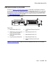
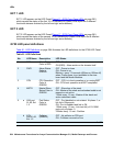
G700 and Media Module LEDs
Issue 1 June 2005 291
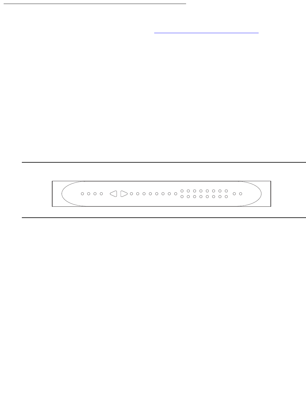
Front panel LEDs
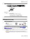
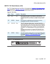
The front panel includes the following LEDs (Figure 17: G700 Front Panel LEDs on page 291):
● 4 LEDs in Voice/Data Module zone (ALM, PWR, CPU, MSTR)
Note:
Note: The LEDs labeled OPR and SYS on the P330 are labeled CPU and MSTR,
respectively, on the G700.
● 16 LEDs representing the Data Ports associated with the Personality Module or Data
Expansion Ports
● 8 LEDs in Data Function zone (LNK, COL, Tx, Rx, FDX, FC, Hspd, LAG)
● 2 LEDs (EXT 1 and EXT 2) for two 10/100 Mb data ports on the chassis
Note:
Note: The four LEDs (ALM, PWR, CPU, MSTR) are positioned as closely as possible to
the top left corner of the LED Panel so that important motherboard-related
information can be quickly located by the service technician.
Figure 17: G700 Front Panel LEDs
A total of 30 LEDs appear on the LED Panel for the G700. The following three LEDs have been
added to the Avaya Cajun LEDs (see “Avaya P330 Manager User Guide”):
● RED ALM or Alarm LED
● EXT 1 LED
● EXT 2 LED
The G700 MSTR LED differs from the Avaya Cajun LED in that the bottom G700 in a stack of
10 G700s with the same version firmware is always elected master (therefore, its MSTR light is
lit). But, if the firmware versions are not the same, the G700 with the latest firmware version is
elected master and its MSTR light is lit. If there is only one G700 in a stack, its MSTR light is
always lit.
ledcled KLC 031402
ALM PWR
CPU MSTR
LNK COL Tx Rx FDX FC Hspd LAG EXT 1
51 52 53 54 55 56 57 58
59 60 61 62 63 64 65 66
EXT 2