


Communication Manager Maintenance-Object Repair Procedures
1078 Maintenance Procedures for Avaya Communication Manager 3.0, Media Gateways and Servers
The DS1 converter circuit pack can be placed in any regular slot in a PN carrier. However, the
DS1 converter circuit pack can only be placed in slots 1 and 21 in a Switch Node (SN) carrier.
The DS1 converter circuit pack is not connected to the TDM bus or the SN backplane.
Communication to the circuit pack is done through the connected EI or the SNI circuit packs.
Therefore, there is considerable interaction between the DS1 converters and the connected EIs
and the SNIs. A special “Y” cable connects the DS1 converter circuit pack to the Fiber Endpoint
and to the facilities.
Note:
Note: The two DS1 converter boards, TN1654 and TN574, use unique “Y” cables that
are incompatible with each other.
The TN573 SNI circuit pack is incompatible with the TN1654 board. A TN573B (or
higher-suffixed) SNI board must be used when connecting to a TN1654 board. The TN573B
SNI board is fully backward compatible with the TN573 board and can be connected to either
TN1654 or TN574 boards.
Note:
Note: A TN573B (or higher-suffixed) board must be used when connecting a SNI board
to a TN1654 board. Error 125 will be logged and an on-board minor alarm will be
generated against the SNI board if it is incompatible with the TN1654 circuit pack.
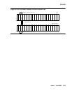
Figure 56: DS1 converter Complex in Direct Connect PNC
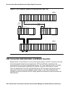
on page 1079 and Figure 57: DS1
Converter Complex in Duplicated PNC with 1 SN on page 1080 show DS1 converter
connections in a direct-connect PNC configuration and between the CSS and an PN in a
critical-reliability system configuration (duplicated PNC).
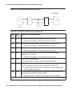
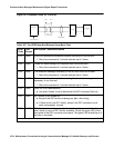
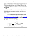
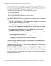
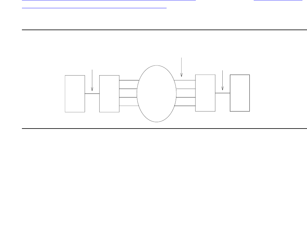
Figure 55: DS1 converter connection to EIs and SNIs
Metallic or Fiber Connection
DS1CONV
DS1 Facilities
Network
EI
or
SNI
EI
DS1CONV
Metallic or Fiber Connection