


DS1C-BD
Issue 1 June 2005 1077
DS1C-BD
S8700 MC only
Also called DS1 Converter
The DS1 converter complex is part of the port-network connectivity (PNC) consisting of two
TN574 DS1 Converter or two TN1654 DS1 Converter circuit packs connected by one to four
DS1 facilities. It is used to extend the range of the 32-Mbps fiber links that connect PNs to the
Center Stage Switch, allowing PNs to be located at remote sites.
The TN1654 DS1 Converter Circuit pack is a redesign of the TN574 DS1 Converter board. The
TN1654 provides functionality equivalent to the TN574 but also adds a 32-channel E1 interface
for international support as well as circuit-switched wideband connections (NxDS0). The
TN1654 is supported beginning with DEFINITY Release 5r.
Every error condition reported by the firmware is associated with background tests that the
firmware runs autonomously. Demand tests that are executed by the maintenance software do
not cause any new error generation by the firmware. However, Failure Audit test (#949) affects
auditing of the software error log by forcing the firmware to report the pending errors again.
Maintenance of the DS1 facilities themselves is covered under the “DS1-FAC” MO.
The DS1 converter complex can extend a fiber link between two EIs or between a PN EI and an
SNI. Fiber links between two SNIs or between a PN and the Center Stage Switch (CSS) cannot
be extended.
The TN1654 board is not compatible with the TN574 board. A DS1 converter complex may
consist of two TN574 boards or two TN1654 boards, but a TN574 cannot be combined with a
TN1654 in the same complex. A system with multiple DS1 converter-remoted PNs may contain
DS1 converter complexes of both types, TN1654 board-pairs and TN574 board-pairs.
Critical-reliability configurations with a pair of DS1 converter complexes serving an PN require
identical board pairs and facilities. For example, a TN574 complex and a TN1654 complex may
not be used together to serve the same PN in a critical-reliability configuration.
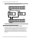
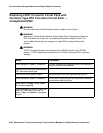
DS1 converter circuit packs connect to TN570 Expansion Interface (EI) circuit packs and TN573
Switch Node Interface (SNI) circuit packs via metallic cables as shown in Figure 55: DS1
converter connection to EIs and SNIs on page 1078. A fiber link cable can be used instead of
the metallic cable if it is necessary to locate the DS1 converter far from the connected EI or SNI
circuit pack, for example, in an adjacent cabinet.
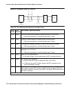
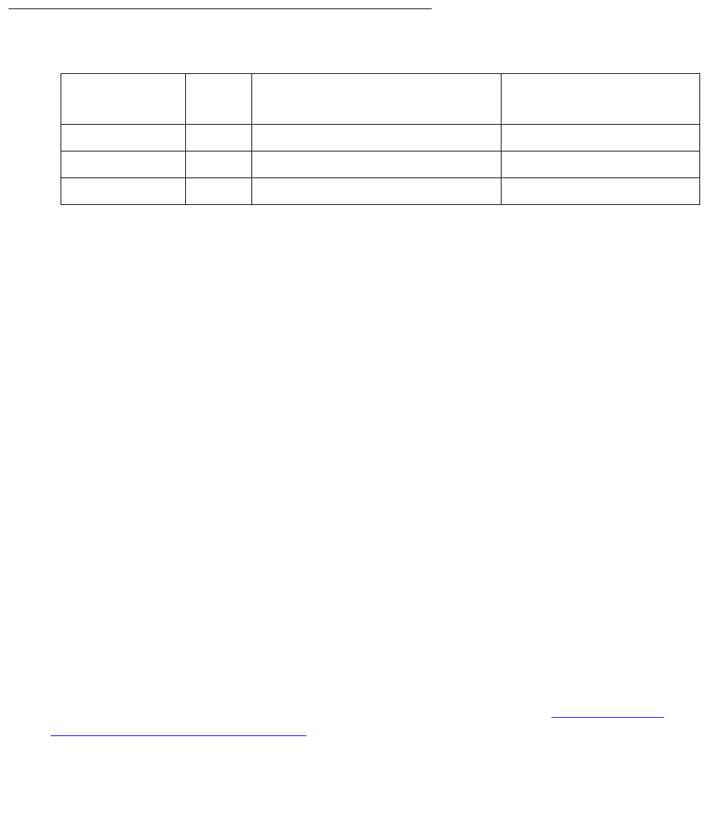
MO Name in
Alarm Log
Alarm
Level
Initial SAT Command to Run Full Name of MO
DS1C-BD MAJ test board location sh r 1 DS1 converter circuit pack
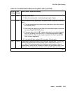
DS1C-BD MIN test board location sh r 1 DS1 converter circuit pack
DS1C-BD WRN test board location sh r 1 DS1 converter circuit pack