


DS1-FAC (DS1 Facility)
Issue 1 June 2005 1053
DS1-FAC (DS1 Facility)
S8700 MC
The DS1-FAC is a part of the DS1 Converter (DS1C-BD) complex. The DS1C-BD complex
consists of two TN574 DS1C-BD circuit packs or two TN1654 DS1C-BD circuit packs
connected by one to four DS1 facilities. The MO name for the DS1 converter circuit pack is
DS1C-BD, and the MO name for the connected DS1 facilities is DS1-FAC.
The TN1654 DS1 Converter circuit pack is a redesign of the TN574 DS1 Converter board. The
TN1654 provides functionality equivalent to the TN574, and adds a 32-channel E1 interface for
international support as well as circuit-switched wideband connections (NxDS0).
The TN1654 DS1 converter circuit pack is not compatible with the TN574 DS1 converter board
or the Y-cable used to interface to the TN574 DS1 converter. A TN573B (or higher-suffixed) SNI
board must be used when connecting to the TN1654 DS1 converter board. See DS1C-BD for
information about both DS1 converter circuit packs.
The DS1 converter complex is a part of the port-network connectivity (PNC). The DS1 converter
complex is used to extend the range of the 32-Mbps fiber links that connect PNs to the Center
Stage Switch, allowing PNs to be located at remote sites.
The DS1 converter circuit pack contains on-board firmware that detects DS1 facility alarms and
errors, communicates status to maintenance software, and runs either background or
on-demand tests from maintenance software. The overall maintenance software strategy
includes demand tests, recovery strategies, error and alarm logging, and periodic audits.
Every error condition reported by the firmware is associated with the background tests that the
firmware runs autonomously. Demand tests that are executed by the maintenance software do
not have any functionality that would effect any additional error manipulation by the firmware.
However, the Failure Audit test (#949) affects auditing of the software error log by forcing the
firmware to report the pending errors again.
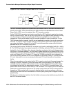
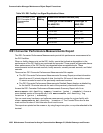
DS1 converter circuit packs are connected to the Expansion Interface (EI) circuit packs (TN570)
and the Switch Node Interface (SNI) circuit packs (TN573) as shown in Figure 50: DS1
Converter Complex and the DS1 Facilities on page 1054.
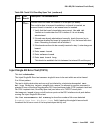
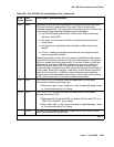
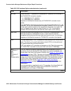
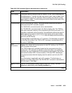
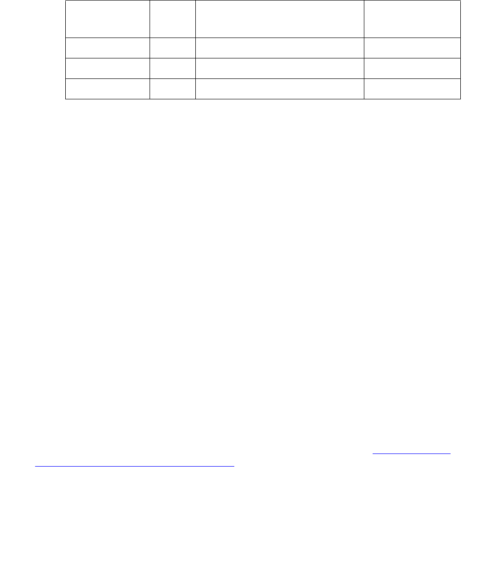
MO Name in
Alarm Log
Alarm
Level
Initial SAT Command to Run Full Name of MO
DS1-FAC MAJ test board location sh r 1 DS1 Facility
DS1-FAC MIN test board location sh r 1 DS1 Facility
DS1-FAC WRN test board location sh r 1 DS1 Facility