


DS1-FAC (DS1 Facility)
Issue 1 June 2005 1073
Near-End External Loop-Back Test (#799)
This test is destructive.
This test starts at the DS1 converter circuit pack whose equipment location was entered and
traverses over the specified facility and loops back at the manually hard-wired external
loop-back device. Depending on the type of physical connectivity of the DS1 facility, special
tools, cables or connectors may be required to make the hard-wired loop backs.
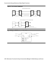
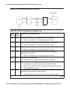
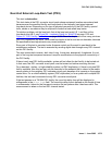
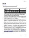
To isolate a problem, set the loop back first at the loop-back point LB 1, and then at the
loop-back point LB 2, see Figure 54: Loopback Points for Test #799
on page 1074 and
Figure 51: DS1 Facility Connections
on page 1068. Place the loop backs at as many points as
your CSU capabilities will allow. Hard-wired loop backs at the far end are not desirable, because
the equalization-level adjustments may cause problems.
Every part of this test is executed under firmware control and the result is sent back to the
maintenance software. The test is executed by sending digital data through every DS1 channel
on this DS1 facility.
This test is executed via test ds1-facility location external-loopback. It is not
part of the long test sequence because it requires modifications to the physical connectivity of
the DS1 facility.
If there is only one DS1 facility available, system will not allow the last facility to be busied out.
In that case, the DS1 converter circuit pack must be busied out before executing this test.
For a standard-, duplex-, or high-reliability system (no PNC duplication), if there is only one DS1
facility available, then this test can only be executed at the endpoint that is closer to the media
server relative to the neighbor DS1 converter circuit pack because of its impacts on the system
control links. For a critical-reliability system (PNC duplication) or for a system with multiple DS1
facilities, the test can be executed at any DS1 converter circuit pack.
If the test passes on a TN1654 DS1 facility, the round trip delay time will be displayed in
milliseconds in the Error Code field. The round trip delay time is defined as the length of time
in milliseconds it takes for the firmware to receive the test pattern after it has been sent. This
measurement is taken on the last DS1 channel tested.