


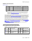
TONE-PT (Tone Generator)
Issue 1 June 2005 2353
TONE-PT (Tone Generator)
S8700 | 8710 / S8500
Note:
Note: Replacing the IPSI or Tone-Clock circuit pack requires a special procedure which
is described in TONE-BD (Tone-Clock Circuit)
on page 2327. That section also
describes the LED display for this board.
The tone generator resides on the IPSI or Tone-Clock circuit pack and provides all system tones
such as dial tone, busy tone, and so on. If an active tone generator fails, its port network may
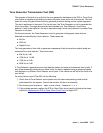
not have tones (see the Tone Generator Transmission Test (#40)
on page 2357. For instance, a
user may go off-hook and hear no dial tone. This problem will affect only users on the same port
network where the faulty IPSI or Tone-Clock circuit pack resides. The system will be able to
process certain type of calls (that is, internal calls will succeed while outgoing calls will not).
The IPSI or Tone-Clock circuit pack also provides the clocks for the system and can serve as
the synchronization reference. Therefore, when resolving alarms, use the TDM-CLK (TDM Bus
Clock) on page 2252, SYNC (Port-Network Synchronization) on page 2143, and TONE-BD
(Tone-Clock Circuit) on page 2327.
See TONE-BD (Tone-Clock Circuit)
on page 2327 for a discussion of the relationship of
Tone-Clock circuit packs with the various reliability options.
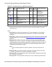
Error Log Entries and Test to Clear Values
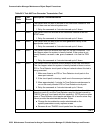
MO Name Alarm Level Initial SAT Command to Run Full Name of MO
TONE-PT MAJ test tone-clock location sh Tone Generator
TONE-PT MIN test tone-clock location sh Tone Generator
TONE-PT WRN release tone-clock location Tone Generator
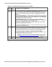
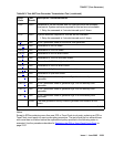
Table 842: Tone Generator Error Log Entries
Error
Type
Aux
Data
Associated Test Alarm
Level
On/Off
Board
Test to Clear Value
0 (a
)0Any AnyAnytest tone-clock
location
1
r 1
1 (b
) 17664 Tone Generator Audit/
Update (41)
MAJ
MIN
2
ON test tone-clock
location r 2
1 of 2