Communication Manager Maintenance-Object Repair Procedures
1586 Maintenance Procedures for Avaya Communication Manager 3.0, Media Gateways and Servers
MG-BRI (BRI Trunk Media Module MM720)
S8700 | 8710 / S8500 / S8300 / G350 / G700
The MM720 BRI Media Module contains eight ports that can be administered either as BRI
trunk connections or BRI endpoint (telephone and data module) connections.
Note:
Note: The MM720 BRI Media Module cannot be administered to support both BRI
trunks and BRI endpoints at the same time. Also, the MM720 BRI Media Module
does not support combining both B-channels together to form a 128-kbps
channel. Finally, if the MM720 BRI Media Module is administered to support BRI
endpoints, it cannot be used as a clock synchronization source.
For BRI trunking, the MM720 BRI Media Module supports up to eight BRI interfaces, or up to 16
trunk ports, to the central office at the ISDN S/T reference point.
For BRI endpoints, each of the 8 ports on the MM720 BRI Media Module can support one
integrated voice/data endpoint or up to 2 BRI stations and/or data modules. Supported
endpoints must conform to AT&T BRI, World Class BRI, or National ISDN NI1/NI2 BRI
standards. The MM720 BRI Media Module provides -40 volt phantom power to the BRI
endpoints.
Information is communicated in two ways:
● Over two 64-kbps channels, called B1 and B2, that can be circuit-switched simultaneously
● Over a 16-kbps channel, called the D-channel, that is used for signaling
The circuit-switched connections have an A- or Mu-law option for voice operation. The circuit-
switched connections operate as 64-kbps clear channels when in the data mode.
LEDs
The three LEDs on the Media Module faceplate indicate board status. When illuminated, the red
LED indicates a board failure or a major or minor on-board alarm, the green LED indicates that
testing is in progress, and the amber LED indicates that the board is in use.
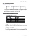
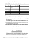
MO Name in
Alarm Log
Alarm
Level
Initial Command to Run Full Name of MO
MG-BRI MIN test board location MO_MG_BRI


