


CABINET (Cabinet Sensors)
Issue 1 June 2005 759
Variable-Speed Fans
A variable-speed fan is identified by the following features:
● A fan and air filter assembly with product code ED-67077-30, Group 4 or greater, labeled
on the front of the carrier
● A 5-pin white connector mounted next to each fan on the fan assembly cover plate for
speed control and alarm circuitry
● A 2-pin black -48 V power connector to each fan
● A power filter (ED-1E554-30, G1 or G2) located in a metal box mounted behind the fans on
the right-hand cable trough as you face the rear of the cabinet
● The AHD1 circuit pack and the two S4 sensors used with older fan assemblies are absent.
Alarm leads from each fan are tied together into a single lead that registers a minor alarm
against CABINET whenever a fan’s speed drops below a preset limit or fails altogether.
Note:
Note: The front fans may run at a different speed than the rear fans since they are
controlled by different sensors.
Note:
Note: Fan/filter replacement procedures for the CMC1 and G600 media gateways are
to be found under Variable-speed fans
Maintenance Procedures (03-300192).
Error Log Entries and Test to Clear Values
S8700 | 8710 / S8500
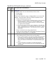
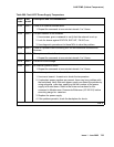
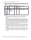
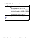
Table 262: S8700 | 8710 / S8500: Cabinet Sensors Error Log Entries
Error
Type
Aux
Data
Associated Test Alarm
Level
On/Off
Board
Test to Clear Value
0 0 Any Any Any test environment UU
1 0 or 1 Cabinet Temperature Query
(#122)
MIN ON test environment UU s r 3
257 0 or 1 Cabinet Temperature Query
(#122)
MAJ ON test environment UU s r 3