


Communication Manager Maintenance-Object Repair Procedures
1066 Maintenance Procedures for Avaya Communication Manager 3.0, Media Gateways and Servers
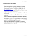
facility is attached. If the NI does not occur at this point, then any cabling between the
CSU terminals and the NI is also considered to be part of the CPE. This cable typically
runs between the DS1 facility terminals of the CSU and a cross-connect field where the
DS1 facility vendor has terminated the DS1 facility. Maintenance responsibility for this
portion of the DS1 facility resides with the customer unless other arrangements are
made.
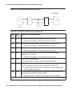
3. If the CPE side LOS indication on CSU B is on (active), check for a problem between the
CPE side of CSU B and the DS1 converter B circuit pack. Connectors, cables, and the
CSU B may need to be replaced.
4. If the CSU A and the CSU B do not provide visual CPE side and DS1 facility side LOS
indications, follow the repair procedure that is given for Error Type1025 (loss of frame
alignment). Apply the procedure first to the DS1 converter B side instead of the DS1
converter A where the error is reported (external loop-back test is not expected to pass if
we execute it at this end as long as we have the LOS indication).
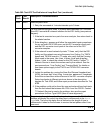
Repair procedure for Error Type #1025 (loss of frame alignment) includes execution of
the Near-End External Loopback test (#799). If this is not a critical-reliability system and
if there is only one DS1 facility, then Test #799 can only be executed at the end that is
closer to the media server relative to the DS1 converter circuit pack at the end of the DS1
converter complex. If the test cannot be executed for that reason, then still make the
external loop back as if the test was going to be executed, but instead of executing the
test, check the green LED at the face plate of the DS1 converter B that is associated with
this DS1 facility. If the green LED is off, then replace the connectors, cables, and the
CSU B.
5. If the problem still persists, replace the DS1 converter circuit pack at the other end of the
DS1 converter complex.
6. If the problem still persists, replace this DS1 converter circuit pack.
If D4 framing is used, an in-band alarm signal (RFA) is transmitted that corrupts transmit
data in response to this alarm.
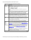
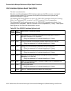
k. Error Type 2065: More than 17 misframe errors occurred. This error will clear when there
are no misframes for 1 hour.
1. Enter display errors and follow the associated repair procedures for any SYNC,
TDM-CLK, or SNC-BD errors.
2. Verify that the DS1 facility and the network are using the same Line Coding. For TN574
boards and TN1654 boards in T1 mode, also verify that the Framing Mode used is the
same. Use list fiber-link and display fiber-link to check the values for this
DS1 facility. Contact T1 Network Service to check the modes used by the network. See
the previous sections, “Line Coding
on page 1059 and Framing Mode on page 1059 for
details on how these options apply to the TN574 and TN1654 DS1 converter boards.
3. For TN574 boards and TN1654 boards in T1 mode, check line equalization settings as
described in the previous section DS1 Converter-1 and DS1 Converter-2 Line
Compensation on page 1058.