


Communication Manager Maintenance-Object Repair Procedures
1422 Maintenance Procedures for Avaya Communication Manager 3.0, Media Gateways and Servers
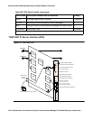
4-Character LED
The 4-character LED is used to display the circuit pack status related to the Ethernet interfaces.
If automatic IP address assignment via DHCP is enabled, the top character displays the Switch
ID and the next two characters display the Cabinet Number. The last character is used to
display the link status of the two Ethernet interfaces.
Services Interface
The top RJ45 jack is the services interface. This is a 10/100 BaseT Ethernet interface.
Control Network Interface
The bottom RJ45 jack is the control network interface. This is a 10/100 BaseT Ethernet
interface. This interface is active only when the IPSI I/O adapter is not plugged onto the
Amphenol connector, located on the rear of the carrier.
PN’s Maintenance Board Interface
The PN’s Maintenance board interface is a header on the IPSI circuit pack with a slit on the
faceplate of the IPSI for the ribbon cable to connect to the PN’s TN775D Maintenance board.
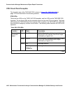
Error Log Entries and Test to Clear Values
System Technician-Demanded Tests:
Descriptions and Error Codes
There is no system technician demand test for this MO.
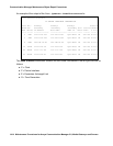
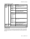
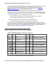
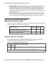
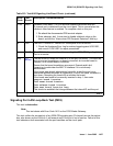
Table 510: LIC-ERR Error Log Entries
Error Type Aux
Data
Associated Test Alarm
Level
On/Off
Board
Test to Clear Value
18
The IPSI circuit pack
is busied out by
maintenance
personnel.
0 busyout
ipserver-in
terface
location
WRN OFF release
ipserver-interface
location