


MMI-SYNC
Issue 1 June 2005 1675
MMI-SYNC
S8700 | 8710 / S8500
Note:
Note: Refer to Chapter 4: General troubleshooting in Maintenance Procedures
(03-300192) for MMCH troubleshooting information.
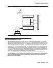
Each Port Network (PN) must have a TN787D or later MMI circuit pack assigned as the
Multimedia Interface (MMI) master synchronization source for that PN. If one or more MMI
circuit pack is administered in a PN, one MMI circuit pack is designated as the master
synchronization source for every MMI circuit pack within that PN.
The MMI circuit pack generates a synchronization signal and puts that signal on the TDM bus.
Other MMI packs or any other circuit pack within a PN can listen to this signal and “synchronize
up” to it. The first MMI circuit pack inserted in a PN is normally designated as the master. As
subsequent MMI packs are inserted, they are instructed to listen and synchronize to the
time-slot of the master MMI. In the unlikely case of an MMI losing this reference, an uplink
message is sent from the MMI circuit pack that lost the signal to maintenance, which also clears
the “event” counter on this MMI with a downlink message. This forces the MMI circuit pack to
return the current state of the synchronization signal. If the signal is still lost, then the recovery
algorithm is entered. Note that during this time, the MMI circuit pack synchronizes to its internal
clock, and there should be no service disruption. A loss of synchronization is usually the result
of a circuit pack failure. The maintenance strategy is to switch the master source away from the
bad pack to another healthy MMI circuit pack within the PN.
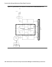
A synchronization switch takes place if half or more of the MMI circuit packs in a PN report a
loss of synchronization. For example, a PN with two MMIs reporting a loss of sync source
switches immediately, three and four MMIs switch if two report the loss, and so forth. A healthy
MMI circuit pack becomes the master synchronization source providing the signal on a new
timeslot. The other MMI circuit packs within the PN are instructed to listen to this new signal,
and the old master stops providing the signal and now listens to the new master MMI. If an MMI
is physically removed from the system, then the remaining MMIs report the loss of
synchronization. The first MMI with no alarms present becomes the new master of that PN.
Once a synchronization switch has occurred, another switch is not allowed for 15 minutes to
avoid hyperactive switching. If every MMI has an alarm, then no switch is made.
If the MMI circuit pack that provides synchronization is craft busied out, it will not affect the PN
synchronization. The signal is still provided by the busied-out pack. There is no effect on
synchronization if the technician enters a release of the busied-out MMI. Synchronization is not
affected by a warm start of the system (reset system 1). For every other restart (reboot through
cold 2), MMI synchronization recovers during board insertion.
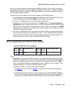
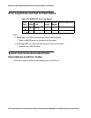
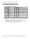
MO Name in
Alarm Log
Alarm
Level
Initial SAT Command to Run Full Name of MO
MMI-SYNC MIN test board location l r# Multimedia Interface circuit pack