


Communication Manager Maintenance-Object Repair Procedures
2432 Maintenance Procedures for Avaya Communication Manager 3.0, Media Gateways and Servers
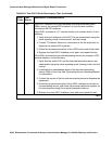
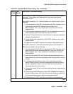
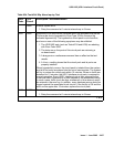
FAIL If the UDS1 connects to a T1 network facility or to another switch, do the
following:
1. The performance of the DS1 link between the UDS1 interface circuit
pack and the remote DS1 endpoint is very poor. Enter list
measurement ds1-log location to read the error seconds
measurement.
2. Verify that both endpoints of the DS1 link are administered using the
same signaling mode, framing mode, and line coding.
3. Contact T1 Network Service or the technician at the remote switch to
diagnose the equipment.
4. Check the physical connectivity of the UDS1 interface circuit packs
and the cable.
5. Replace the local UDS1 interface circuit pack, and repeat the test.
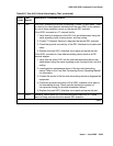
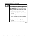
If the UDS1 connects to a line-side terminating device (for example, a
PRI terminal adapter), do the following:
1. The performance of the DS1 link between the UDS1 interface circuit
pack and the line-side terminating device is very poor. Enter list
measurement ds1-log location to read the error seconds
measurement.
2. Verify that the switch DS1 and the line-side terminating device are
administered using the same signaling mode, framing mode, and
line coding.
3. Investigate the maintenance status of the line-side terminating
device. Refer to the 'Line-Side Terminating Device Operating
Manual' for information.
4. Contact the vendor of the line-side terminating device to diagnose
the equipment.
5. Check the physical connection of the UDS1 interface circuit pack to
the terminating device, and check the premise distribution system (or
the intra-premise wiring) for physical connection failures.
6. Replace the local UDS1 interface circuit pack and repeat the test.
PASS No Major alarm is detected in the UDS1 Interface circuit pack.
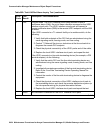
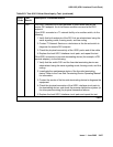
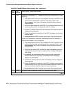
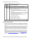
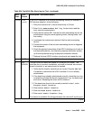
Table 862: Test #142 Major Alarm Inquiry Test (continued)
Error
Code
Test
Result
Description / Recommendation
2 of 3