


LEDs
262 Maintenance Procedures for Avaya Communication Manager 3.0, Media Gateways and Servers
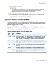
The yellow LED is used to indicate the state of the fiber interface, the fiber channel, and the
DS1 channel as listed in Table 66: DS1C yellow LED flashing states
on page 262 in order of
priority.
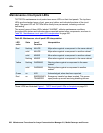
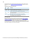
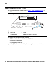
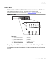
DS1 Facility LEDs
Below the three standard LEDs on the DS1C circuit pack are four green LEDs that indicate
whether a receive signal is present for each of the four DS1 facilities. Figure 2: TN574 DS1
Converter circuit pack LEDs on page 263 shows which facility (A, B, C, or D) corresponds to
each LED. If a green LED is off, there is a Loss of Signal condition on the DS1 facility
associated with that LED. The presence of a signal does not guarantee that the signal is using
the correct framing format or line coding; an Alarm Indication Signal indicating that the opposite
end of the DS1C complex is out of service may be present.
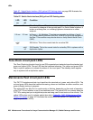
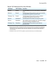
Table 66: DS1C yellow LED flashing states
LED
on
LED
off
Condition
0.1 sec 0.1 sec Fiber Out-of-Frame or Fiber Loss of Signal
0.5 sec 0.5 sec In Frame, fiber channel down. The fiber channel communicating between
the DS1C and the other fiber endpoint (EI or SNI) is down.
1 sec 1 sec In Frame, DS1 channel down. The channel between the two DS1Cs in the
DS1C complex is down.
solid on DS1C active. This is the normal state for an active DS1C.
solid off DS1C standby. This is the normal state for a standby DS1C in
critical-reliability systems (duplicated PNC).