


DS1-FAC (DS1 Facility)
Issue 1 June 2005 1063
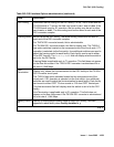
f. Error Type 856: More than 88 negative and/or positive slip errors occurred. This error
clears when there are no slips for 1 hour.
1. Enter display errors and follow the associated repair procedures for any SYNC,
TDM-CLK, and SNC-BD errors.
2. Verify that the DS1 facility and the network are using the same Line Coding. For TN574
boards and TN1654 boards in T1 mode, also verify that the Framing Mode used is the
same. Use list fiber-link and display fiber-link to check the values for this
DS1 facility. Contact T1 Network Service to check the modes used by the network. See
the previous sections, “Line Coding” and “Framing Mode” for details on how these
options apply to the TN574 and TN1654 DS1 converter boards.
3. For TN574 boards and TN1654 boards in T1 mode, check line equalization settings as
described in the previous section, “DS1 converter-1 and DS1 converter-2 Line
Compensation.”
4. Enter display errors and follow the associated repair procedures for any EXP-INTF,
and SNI-BD errors for the Fiber Endpoints. Enter display errors and follow the
associated repair procedures for any FIBER-LK errors for this fiber link.
5. If the problem still persists, replace this DS1 converter circuit pack.
6. If the problem still persists, replace the DS1 converter circuit pack at the other end of the
DS1 converter complex.
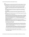
g. Error Type 1025: Loss of Frame Alignment (LFA) Alarm, the RED alarm. This alarm
indicates that the DS1 interface associated with the DS1 facility cannot frame up on the
received data.
For the following repair procedure, see to Figure 51: DS1 Facility Connections
on
page 1068 and the diagrams in the related test descriptions.
1. If the network is used instead of private T1 lines, check that the DS1 facility and the
network are using the same line coding. For TN574 boards and TN1654 boards in T1
mode, also verify that the Framing Mode used is the same. For TN1654 boards, verify
that the two boards in the DS1 converter complex are using the same bit rate. Use list
fiber-link and display fiber-link to check the values for this DS1 facility.
Contact T1 Network Service to verify the modes set for the network. See the previous
sections, Line Coding
on page 1059, Framing Mode on page 1059, and Bit Rate on
page 1058 for details on how these options apply to the TN574 and TN1654 DS1
converter boards.
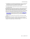
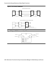
2. Run the Near-End External Loopback test (#799) via test ds1-facility location
external-loopback by setting up a loop back at CPE side of CSU towards DS1
converter circuit pack shown as loop back point LB 1 in the test description diagram. If
the test fails, replace connectors and the cables between CSU and the DS1 converter
circuit pack.
3. If the test passes, run the Near-End External Loopback test (#799) via test
ds1-facility location external-loopback by setting up a loop back at DS1
facility side of CSU towards the DS1 converter circuit pack shown as loop-back point LB
2 in the test description diagram. If the test fails, replace the CSU.