


EXP-INTF (Expansion Interface Circuit Pack)
Issue 1 June 2005 1195
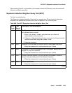
b. Error Type 23: EI circuit pack has been administered on the Circuit Pack screen, but has
not been physically inserted into the system. Insert the circuit pack.
c. Error Type 125: A different circuit pack occupies the slot where this circuit pack is logically
administered. To resolve this problem, either:
1. Replace the incorrect circuit pack with the logically assigned circuit pack.
2. Use change circuit-pack to reassign the slot to match the existing circuit pack. (If a
fiber is assigned for the existing circuit pack, remove the fiber from translations before
changing the circuit pack’s translations.)
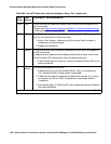
d. Error Type 131: is raised after an EI circuit pack has been removed from a slot for 5
minutes. The alarm will be resolved when the EI circuit pack is physically inserted into this
slot and becomes recognized by software.
Another way to resolve or prevent this alarm is to use change circuit pack to remove
the EI circuit pack administrative entry for this slot after the EI circuit pack has been
removed from the slot.
It is also possible that the EI could be held in reset by the PN’s Maintenance board (MAINT)
and is not inserted in the system. Enter test maint P long on the Maintenance board in
the same PN.
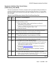
e. Error Type 257 indicates that this EI circuit pack is detecting incorrect data on the incoming
fiber bit stream. The data is originating at the connected circuit pack (DS1 converter circuit
pack, EI circuit pack, or SNI circuit pack).
1. Enter display errors and save a copy of the error log for use in later steps.
Intervening repair procedures are likely to alter the contents of the error log and this
information may be needed in later steps.
2. Perform the Fiber link fault isolation
in Maintenance Procedures (03-300192).
3. If errors are still present or if this error occurs intermittently, replace the EI circuit packs,
SNI circuit packs, DS1 converter circuit packs, or the transceivers on this link.
4. These errors could result from a bad timing reference on the network or switch node that
contains the DS1 converter circuit pack, the EI circuit pack or SNI circuit pack on the
opposite end of the fiber. Refer to the error log that was saved in step 1 and follow the
associated repair procedure for EXP-INTF error 2305 to resolve this error. If there are
any TONE-BD, TDM-CLK, or SYNC errors, resolve these errors as well.
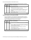
f. Error Type 513 with Aux Data 5–7— Indicates an ON BOARD hardware failure of the circuit
packs RAM or ROM.
1. Replace the EI circuit pack.
g. Error Type 769: Besides running the test sequence and following procedures outlined for
Test #238, perform the Fiber link fault isolation
in Maintenance Procedures (03-300192).
h. Error type 1281: The link to the neighbor circuit pack is broken or that the fibers have been
connected incorrectly. Enter test board location and follow repair procedures for the
tests.