


Communication Manager Maintenance-Object Repair Procedures
2436 Maintenance Procedures for Avaya Communication Manager 3.0, Media Gateways and Servers
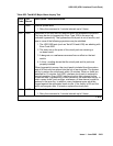
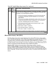
Slip Alarm Inquiry Test (#144)
Slips occur when the transmitter and receiver are not running at precisely the same clock rate.
The UDS1 Interface circuit pack can detect both positive and negative slips on the DS1 facility.
The Slip Alarm Inquiry test is used to acquire the total number of slips that have occurred on a
DS1 link.
When the UDS1 Interface circuit pack detects a slip condition, the circuit pack increments the
on-board slip counter by one. A SLIP-COUNT message is spontaneously sent to the system
software after the counter reaches a threshold (for example, 88). When the maintenance
software receives the SLIP-COUNT message, the Slip Alarm Inquiry test is initiated to query the
slip counters on a UDS1 Interface circuit pack and total the slip counts in the maintenance
software.
If the count of slips is over the threshold, a Minor alarm is raised against the UDS1 Interface
circuit pack. Every trunk or port of the UDS1 Interface circuit pack remains in the in-service
state. If the UDS1 Interface circuit pack is used to supply the system synchronization source,
the MINOR alarm will initiate a synchronization source switch. See TDM-BUS (TDM Bus)
on
page 2237 and SYNC (Port-Network Synchronization)
on page 2143 for details.
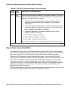
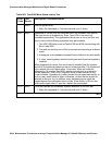
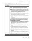
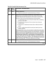
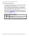
PASS No Minor alarm is detected in the UDS1 Interface circuit pack.
0NO
BOARD
The test could not relate the internal ID to the port (no board). This could
be due to incorrect translations, no board is inserted, an incorrect board
is inserted, or an insane board is inserted.
1. Verify that the board’s translations are correct. Execute add ds1
location to administer the UDS1 interface if it is not already
administered.
2. If the board was already administered correctly, check the error log to
determine whether the board is hyperactive. If so, the board was shut
down. Reseating the board will re-initialize it.
3. If the board was found to be correctly inserted in step 1, enter
busyout board location.
4. Enter reset board location.
5. Enter release board location.
6. Enter test board location long.
This should re-establish the linkage between the internal ID and the port.
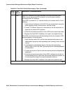
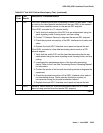
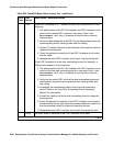
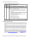
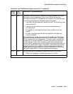
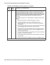
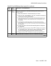
Table 863: Test #143 Minor Alarm Inquiry Test (continued)
Error
Code
Test
Result
Description / Recommendation
3 of 3