


SYNC (Port-Network Synchronization)
Issue 1 June 2005 2165
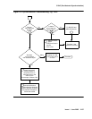
Synchronization Switches away from
Current Timing Reference
Synchronization changes away from a DS1 reference (primary or secondary) if the current DS1
reference does not provide a valid timing signal. The other DS1 reference is used if one is
administered and providing a valid timing signal. Otherwise, the local oscillator of the
Tone-Clock circuit pack in the same port network as the DS1 reference is used. The following
conditions cause a synchronization switch:
● The current DS1 reference is not inserted (list configuration board location
shows no board).
● The current DS1 reference has a loss of signal error (DS1-BD and UDS1-BD Error Type
1281), a blue alarm error (DS1-BD and UDS1-BD Error Type 1793), a red alarm error
(DS1-BD and UDS1-BD Error Type 2049), or a hyperactive angel error (DS1-BD and
UDS1-BD Error Type 1538). A corresponding alarm log entry is not required.
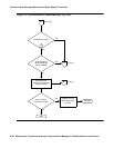
● DS1 and UDS1 circuit packs can be administered with slip detection enabled (the Slip
Detection field is y) on the add ds1 or change ds1 administration screens (See the
Administrators Guide for Avaya Communication Manager - 555-233-506). When over half
of the DS1 and UDS1 circuit packs administered as slip enabled experience slips, and the
primary or secondary synchronization reference is the current synchronization reference,
synchronization tries the other administered synchronization reference if the other
administered reference does not have the previous two conditions. Use list
measurements ds1-log to get an historical perspective of DS1 facility operation.
The following conditions cause a change to the other DS1 reference if one exists and the other
DS1 reference is more healthy:
● The current DS1 reference has a misframe error (DS1-BD Error Type 3329 to 3345 or
UDS1-BD Error Type 3585-3601). A corresponding alarm log entry is not required.
● The current DS1 reference has a slip alarm (DS1-BD and UDS1-BD Error Type 3073 to
3160). A corresponding alarm log entry is required.
If the previous conditions are repaired, synchronization changes back to the primary reference.
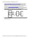
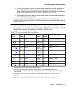
LEDs on Tone-Clock Circuit Packs
The specific flashing pattern of a TN768, TN780, or TN2182 Tone-Clock circuit pack’s amber
and green LEDs indicates the circuit pack’s status. For example, these flashing LED patterns
indicate whether the Tone-Clock circuit pack is:
● Deriving timing from an external source
● Providing the timing signal for its PN