


TONE-BD (Tone-Clock Circuit)
Issue 1 June 2005 2341
Note:
Note: For a critical-reliability system (duplicated PNC), the system generally expects a
PN to have its “preferred” Tone-Clock circuit pack active. For the first PN in a
given cabinet, this is carrier A. For a second PN in the cabinet, this is carrier E.
b. status system
— Verify the Tone-Clock circuit pack switched to the other Tone-Clock
circuit pack or check the LEDs. The amber LED of the new standby Tone-Clock circuit
pack should be off (provided maintenance is not running on it) and the amber LED of the
active Tone-Clock circuit pack should be blinking.
c. If the interchange was not successful, the standby Tone-Clock circuit pack may be
defective. In particular, if the error message must use override is displayed, fix the
standby Tone-Clock circuit pack before attempting to replace the active one.
2. Pull out the defective Tone-Clock circuit pack. No calls should be affected. If this is a
TN2182 circuit pack, some ETR-PTs may be in use and removal of the pack will affect some
individual users. It may be less disruptive to busyout the standby TN2182 before removing
it.
3. Insert a new Tone-Clock circuit pack of the appropriate code in the same slot where the
defective Tone-Clock circuit pack was removed.
4. Test the new Tone-Clock circuit pack using test tone-clock location long to make
sure it is functioning properly. If the Tone-Clock circuit pack is being replaced due to loss of
clocks, the Clock Health Inquiry (#46) will still report a failure, proceed with the next step.
5. To verify that the new Tone-Clock circuit pack can generate clocks for the system, switch to
the new Tone-Clock with set tone-clock location override, and execute test
tone-clock location. If the new Tone-Clock circuit pack is able to generate system
clocks, there will be no system disruption.
!
CAUTION:
CAUTION: If the new Tone-Clock circuit pack is not able to generate system clocks, this
procedure becomes destructive. The system will detect a loss of clock and
recover by resetting the PN (PN cold restart).
After the restart, the faulty Tone-Clock circuit pack will be in standby mode.
6. Place several phone calls.
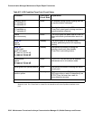
IPSI/Tone Clock LED States
For the TN2312 IPSI circuit pack, there are four LEDs on the IPSI’s faceplate. The top three
LEDs are the standard ones found on any TN circuit pack. The fourth LED imitates the
TN2182B Tone-Clock’s amber LED. The active/standby state of an IPSI or Tone-Clock circuit
pack may also be determined by looking at its LEDs. A continuously lit red LED on the circuit
pack indicates a reported fault on one or more of its MOs. Flashing patterns of the yellow and
green LEDs correspond to the following service states: