Communication Manager Maintenance-Object Repair Procedures
1992 Maintenance Procedures for Avaya Communication Manager 3.0, Media Gateways and Servers
SN-CONF (Switch Node Configuration)
S8700 MC only
A switch node carrier contains:
● Up to 16 Switch Node Interface (SNI) TN573 circuit packs in slots 2 through 9 and slots 13
through 20
● One or two Switch Node Clock (SNC) TN572 circuit packs in slots 10 and 12
● An Expansion Interface (EI) TN570 circuit pack, a DS1 Converter (DS1C) TN574 circuit
pack, or no circuit pack in slot 1
● An optional DS1 converter circuit pack in slot 21
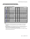
SN-CONF errors and alarms are generated for two types of failures:
1. Failure of a board in the switch node carrier to insert (be detected by software).
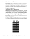
2. A problem found by running the Configuration Audit test (#759). Test 759 is executed for
either an SNI or SNC circuit pack during scheduled maintenance or as part of test board
location.
For SNI circuit packs, test 759 queries the SNI for SNCs in the same switch node carrier,
SNI peers, DS1 converters, and EI or SNI neighbors that the SNI can communicate with
and compares this data to the administered data.
For SNC circuit packs, test 759 queries the SNC for SNCs and SNIs in the same switch
node carrier that the SNC can communicate with and compares this data to the
administered data.
Switch node carriers are part of port-network connectivity (PNC). For background information
about PNC, refer to the Maintenance Architecture and Hardware Configurations chapters and
related MOs.
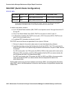
MO Name Alarm Level Initial SAT Command to Run Full Name of MO
SN-CONF MAJ test board location Switch Node Configuration
SN-CONF MIN test board location
1
1. If the error and alarm logs display the switch node carrier location UUC (cabinet and carrier only),
run the long test sequence on the active SNC in the carrier, (slot 10 or 12). If the error and alarm
logs display a circuit pack location, run the short test sequence on the alarmed SNI.
Switch Node Configuration


