


Communication Manager Maintenance-Object Repair Procedures
1418 Maintenance Procedures for Avaya Communication Manager 3.0, Media Gateways and Servers
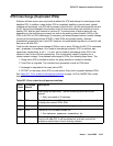
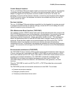
The TN2312BP and the 655A power supply provide the following information to the G650:
● Environment maintenance
- Inlet temperature - Inlet temperature of the G650 (sensor is in the 655A power supply)
- Exhaust temperature - G650 carrier exhaust air sensor
- Hot Spot temperature status- 655A power supply sensor
-Voltage
-+5VDC
--5VDC
--48VDC
- Fan Control - The speed at which the fans are operating:
- Undr indicates that the fan voltage is under 12VDC.
- Mid (normal) indicates that the fan voltage is +12VDC.
- High indicates that the fan voltage is +14VDC.
- Over indicates that the fan voltage is above 14 to 15VDC.
- Fan Alarm - Detection of a blocked or failed fan
- Ring Status - OK, overload, shorted, or failed
- Ring Control - Active, standby, disabled, off (shorted or failed)
- Ringer Setting - 20Hz, 25Hz, or other
- Ring Detection - Reports if the power supply detects ring on the backplane ring leads
- Input Power - Indicates the type of power present and in use, AC or DC
● External device alarm detection
The external device alarm detection uses two external leads. External devices such as an
uninterruptible power supply (UPS) or voice messaging system can use these leads to
generate alarms using the Avaya Communication Manager alarm reporting capability.
Ground potential on either of these leads results in an alarm being generated. You can
administer the alarm level (major, minor, or warning), product ID, alternate name, and alarm
description for each lead.
● Emergency transfer control
Emergency transfer control provides -48VDC to operate an external emergency transfer
panel. The Communication Manager controls the state of the emergency transfer. (Note
that, in the past, hardware boards or alarm panels provided a three-position physical switch
to control emergency transfer.) An emergency transfer status red LED shows when
emergency transfer is active.