


LEDs
288 Maintenance Procedures for Avaya Communication Manager 3.0, Media Gateways and Servers
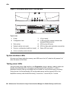
G700 and Media Module LEDs
LEDs are important status indicators for technicians during on-site installation, maintenance,
troubleshooting, and repair. They encompass three major areas: Alarms, Testing, and Usage
Activity. Some LEDs are specialized to support specific procedures (such as removing the
S8300 Media Server). When alarms or problems occur, LEDs are present to indicate that
attention by a technician is needed.
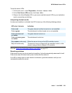
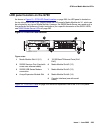
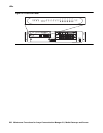
LEDs appear on the G700 LED panel, and each Media Module. The G700 LEDs are the same
as those on the Avaya Cajun P330, with the following exceptions:
● Slight modifications to two of the LEDs (OPR and SYS)
● Addition of the Alarm LED to the LED Panel to display prominently any error condition
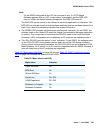
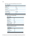
See “Table 2-1: Avaya P333T LED Description, in the "Avaya P333T User’s Guide" for a
complete listing of LEDs.
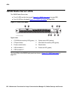
Some Media Modules have additional LEDs, although each Media Module has the three
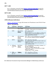
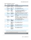
standard LED. Table 80: LED Interpretation
on page 288 indicates the meanings associated
with standard DEFINITY server LEDs. Although in some cases these LEDs have been
augmented or modified for the S8300 Media Server and G700 Media Gateway, it is important to
be aware of their standard meanings when viewing the system.
Note:
Note: The four multi-color specialized status LEDs that have appeared on various
DEFINITY server TN boards like the T1/E1/DS1 board (TN464) do not appear on
the Media Modules.
Note:
Note: LEDs can also be viewed using the embedded Device Manager on the L2
Switching Processor; however, it displays LED position only, and does not
indicate status.
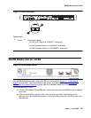
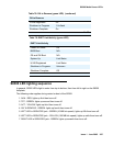
Table 80: LED Interpretation
Red Upon power-up or module insanity, this LED is turned on. Upon passing
diagnostics, this LED is turned off.
Green During power-up self testing and maintenance testing, this LED is turned on.
Yellow This LED indicates that the module is in service.