


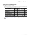

SNI-BD (SNI Circuit Pack)
Issue 1 June 2005 2053
Switch Node Interface Manual Loop Back
Procedure
This procedure is destructive.
Use this procedure when an SNI circuit pack cannot be tested by software. This can occur when
communication between the switch node carrier and the server is down. Before using this
procedure, use test board location s to run the configuration audit test (#759) on SNI
circuit packs where possible. Also, use test board location long to run the processor
route audit test (#760) for the active SNC in the switch node carrier. If the active SNC is not
inserted, use test hardware-group pnc P, where P is a-pnc or b-pnc to run test 760.
Before using this procedure, determine if more than one SNI is unable to communicate with
software. Verify SNI and SNC circuit pack insertion using the list configuration
carrier location where location is the cabinet and carrier location of a switch node
carrier. Check for inserted SNIs and SNCs in every administered switch node carrier.
If every SNI and SNC is not inserted, then “NO BOARD” is displayed for each board in the
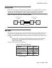
entire PNC (either the a-pnc or the b-pnc). The link between the IPSI connected PN’s EI (on the
PNC where SNI and SNC circuit packs were not inserted) and the connected SNI does not
function properly. If this applies:
1. Run test board location on the IPSI connected PN’s EI, and fix any problems.
2. Perform the manual loopback procedure for the IPSI connected PN’s EI.
3. Perform the manual loopback procedure for the SNI connected to the IPSI connected PN’s
EI.
4. Replace the active SNC.
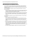
If the system has a 2-level switch node carrier configuration (i.e., SNI-to-SNI fiber links exist)
and the SNIs and SNCs in the second switch node carrier only (the switch node carrier that has
no SNI connected to the IPSI connected PN’s EI) are not inserted and at least two SNI-to-SNI
fiber links exist:
1. Run test board location long on the SNIs in the first switch node carrier that are
connected to SNIs in the second switch node carrier and fix any problems.
2. Replace the active SNC.
3. Perform the manual loopback procedure for the SNIs in the second switch node carrier that
are connected to SNIs in the first switch node carrier.
If software is unable to communicate with a PN’s EI but can communicate with the connected
SNI:
1. Run test board location long on the connected SNI and fix any problems.
2. Perform the manual loopback procedure for the PN EI.
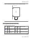
If the connection to the SNI circuit pack is fiber, a short length of optical fiber is required for
this procedure. If a metallic cable is used in the connection, remove the metallic connector
from the back of the carrier, and install a lightwave transceiver in its place. The short length
of optical fiber can then be used.