


UDS1-BD (UDS1 Interface Circuit Pack)
Issue 1 June 2005 2385
The TN464 supports digital Tie, CO, and DID trunks, and OPS lines. On-board firmware
performs call control signaling for the Tie, CO and DID trunks and OPS lines. ISDN-PRI trunk
and PRI-endpoint signaling (Q.921, Q.931) is received and generated by system software and
is transmitted on a system link through the TN1655 Packet Interface and packet bus to the
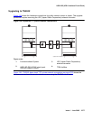
UDS1 where it is placed on the D channel. Signaling over the DS1 link has to be synchronized
between the transmitting and receiving ends to ensure error-free communication. See SYNC
(Port-Network Synchronization) on page 2143 in this MO for details.
Each trunk, line, or endpoint has its own maintenance strategy, but all depend on the health of
the UDS1 Interface circuit pack. See the following Maintenance Objects for details: TIE-DS1
(DS1 Tie Trunk) on page 2270, CO-DS1 (DS1 CO Trunk) on page 817, DID-DS1 (Direct Inward
Dial Trunk) on page 886, OPS-LINE (DS1 Off-Premises Station Line) on page 1736, ISDN-TRK
(DS1 ISDN Trunk) on page 1446, ISDN-PLK (ISDN-PRI Signaling Link Port) on page 1423,
ISDN-SGR (ISDN-PRI Signaling Group)
on page 1429, WAE-PORT (Wideband Access
Endpoint Port) on page 2531 and PE-BCHL (PRI Endpoint Port) on page 1773.
Circuit Pack Administration and Options
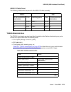
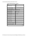
The DS1 configuration for each circuit pack is administered on the DS1 Circuit Pack screen. Bit
Rate is set to 1.544 Mbps for 24-channel systems, and 2.048 Mbps for 32-channel systems.
Country Protocol is used to drive layer-3 protocol decisions based on PRI specifications for a
given country (not those related to specific features). Different UDS1 circuit packs may be
administered with different Country Protocols, allowing the switch to act as a gateway between
two incompatible ISDN-PRI implementations (for example, between two different countries). US
systems use country protocol 1.
Set Near-End CSU Type to other for no CSU installed or for an external CSU such as an ESF
T1 CSU, or set to integrated for the 120A1 CSU module or the 401A T1 sync splitter. Setting
the field to integrated causes additional fields to appear for administering the Enhanced
Integrated CSU module. Set E1 Sync-Splitter to y if a 402A or 403A E1 sync splitter is used to
provide timing to an ATM switch. Set Echo Cancellation to y if the echo cancellation
right-to-use feature is enabled and the TN464GP/TN2464BP or higher suffix board is to supply
echo cancellation.
Note:
Note: Set the Echo Cancellation Plan on the EC Configuration field of the DS1
Circuit Pack screen. Note that Plan 1 uses a 96-ms echo tail and introduces 6dB
of loss for additional cancellation.
In addition, other fields define such parameters as framing modes, line coding, companding
mode and so on. For further details refer to DEFINITY® Communications System Generic 1,
Generic 2 and Generic 3 V1 and 2 – Integrated Channel Service Unit (CSU) Module Installation
and Operation, 555-230-193.