


SER-BUS (Serial communication bus)
Issue 1 June 2005 1961
Serial Bus problem appeared.) Also examine which power supplies the system is unable to
show using list configuration power-supply C and concentrate your efforts on those
carriers and their cabling.
!
CAUTION:
CAUTION: When straightening or replacing backplane pins in a carrier, power to that carrier
must be shut off. Failure to follow this procedure may result in damage to circuit
packs and power supplies, and can be hazardous to the technician.
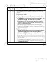
Procedure 1
The procedure removes and reinserts port circuit packs (those in the purple slots) one or more
at a time. Use this procedure for each port circuit pack in the port network until the problem is
resolved or until all circuit packs in the port network have been tried.
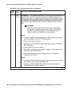
If the Serial Bus problem is present when the circuit pack is inserted, but is resolved when the
circuit pack is removed, either the circuit pack or the backplane pins in that slot are causing the
problem. If the backplane pins are intact, replace the circuit pack. If some of the tests fail
regardless of whether the circuit pack is inserted or removed, and the backplane pins are intact,
the circuit pack is not the cause of the problem. In a multiple failure situation, the circuit pack
could be one cause of the Serial Bus problem. However, other simultaneous failures might also
be responsible for Serial Bus faults. In Procedure 2, an option of working either with one circuit
pack at a time or with multiple circuit packs simultaneously is available. In view of this capability,
determine the level of service interruption that will be acceptable during the procedure. If
causing a disruption to all users in the port network is deemed permissible, large groups of
circuit packs should be worked with in order to get the job done quickly. However, if large
service disruptions are to be avoided, work with one circuit pack at a time. This option is slower,
but it disrupts only the users of a single circuit pack.
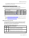
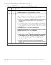
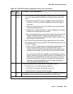
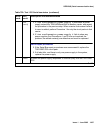
Refer to the repair procedure steps given under Serial bus communications test (#1531)
on
page 1963
.
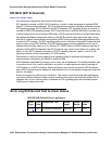
Procedure 2
Procedure 2 attempts to isolate the Serial Bus failure to a particular set of carriers. Only the
circuit packs in selected carriers are checked. Procedure 2 is used if the preceding procedure
fails, because it can help locate multiple circuit pack failures and failures of the carrier hardware
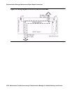
itself. In this procedure, the TDM/LAN Cable Assemblies and TDM/LAN Bus terminators are
replaced. If this action does not resolve the Serial Bus fault, the carriers are reconfigured so that
certain carriers are disconnected from the Serial Bus. This is done by moving the TDM/LAN Bus
terminators (AHF110) on the carrier backplane. To terminate a Serial Bus at the end of a
particular carrier, the Serial Bus cable that connects the carrier to the next carrier should be
unplugged and replaced with the TDM/LAN Bus terminator. When the length of the Serial Bus is
modified the A carrier TN2312BP IPSI circuit pack that is essential to the Serial Bus operation
and Serial Bus maintenance must still be connected to the new shortened Serial Bus.