


SN-CONF (Switch Node Configuration)
Issue 1 June 2005 1997
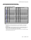
2. If they are not lit, check that the fiber connections to the port network are consistent with the
administered fibers (list fiber-link) that does not light the LEDs as expected.
3. Run test led switch-node on each administered switch node carrier and verify that
the LEDs on the correct carrier are lit.
4. If they are not, check the connectivity to the switch node carrier that does not light the LEDs
as expected.
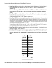
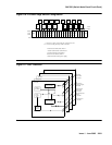
Incorrectly Connected SNI-to-SNI Fibers
between Three Switch Nodes
If the system has more than 2 switch nodes, SNI-to-SNI fibers administered between 2 switch
nodes could be incorrectly connected to a third switch node. This is a problem that could occur
during installation or when inter-switch node fibers are changed. For multiple fibers to a distant
switch node, an incorrect connection would not appear as a problem unless this fiber is used for
a system-link to a port network connected to the distant switch node. Use status sys-link
to determine the boards in the path from an IPSI connected PN to another specific PN. A
specific SNI-to-SNI fiber connection must be in the system-link path to be checked with the port
network LED test.
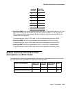
Forcing SNI-to-SNI Fiber Connection
To force an SNI-to-SNI fiber connection to be used as a system-link, remove every SNI-to-SNI
connection except the fiber link being tested at the distant switch node by removing SNI boards
in the distant switch node.
1. Use status sys-link to verify that the fiber selected for test is in the path to the PN
connected to the distant switch node that will be used for the LED test.
2. Run test led to a port network as described above to verify this fiber connection.
3. Repeat the above procedure for each of the SNI-to-SNI fibers terminating on the distant
switch node.
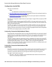
Testing Multiple Fiber Connections
To test multiple fiber connections to a distant switch node:
1. Use list fiber-link to determine the number of SNI-to-SNI fibers that are
administered to and terminate on the distant switch node.
2. Run test led port-network on a PN connected to the distant switch node, and verify
the LEDs on the correct PN are lit.
3. Use status sys-link and select the active EI in the IPSI connected PN connected to
the distant PN under test. (The display will show the path from the IPSI connected PN and
the SNI-to-SNI fiber being used.)