


Communication Manager Maintenance-Object Repair Procedures
2192 Maintenance Procedures for Avaya Communication Manager 3.0, Media Gateways and Servers
TBRI-BD
(TN2185 ISDN Trunk-Side BRI)
S8700 | 8710 / S8500
Note:
Note: G700: The separate, but equivalent MG-BRI MO can reside in slots 1–4 of a G700
media gateway. Refer to MG-BRI (BRI Trunk Media Module MM720)
on
page 1586 for information about the MG-BRI MO.
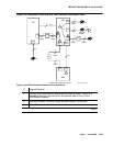
The TN2185 circuit pack contains eight, 4-wire ports that interface to the network at the ISDN S/
T reference point over two 64 Kb/s channels (B1 and B2) and over a 16Kb/s signaling (D)
channel.
The B1 and B2 channels can be simultaneously circuit-switched or individually packet-switched.
Only one channel per trunk can be packet-switched due to PPE (Packet Processing Element)
limitations. The D channel is either circuit-switched or packet-switched. Packet switching uses
the PPE to combine all D channels into a single physical channel, which is then routed via the
concentration highway to the NCE (Network Control Element) and then to the TDM bus. The
circuit-switched connections have a Mu-law or A-law option for voice and operate as 64-kbps
clear data channels. The packet-switched channels support the LAPD protocol and conform
with the CCITT Q.920 Recommendations for D-channel signaling.
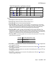
LEDs
The three LEDs on the circuit pack’s faceplate indicate board status. When illuminated, the red
LED indicates a board failure or a major or minor on-board alarm, the green LED indicates that
testing is in progress, and the amber LED indicates that the board is in use.
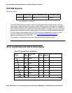
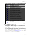
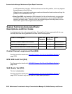
MO Name Alarm Level Initial SAT Command to Run Full Name of MO
TBRI-BD MIN test board location long r# TBRI-BD