


DS1-BD (DS1 Interface Circuit Pack)
Issue 1 June 2005 1001
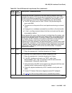
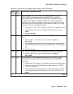
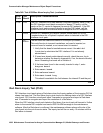
1312 FAIL The Integrated CSU (I-CSU) Module Repeater Loopback (RLB) test
(#1211) failed. This test is executed during ICSU/T1 sync splitter
power-up/reset (the TN767E board is physically inserted and the CSU
module/T1 sync splitter is already installed), or when the 120A1 CSU
module/T1 sync splitter is plugged on to an already initialized DS1 board.
The RLB test is also executed as part of the command test ds1-loop
location ds1/csu-loopback-tests.
1. Execute test ds1-loop location ds1/csu-loopback-tests.
2. If the RLB test continues to fail, replace the CSU module/T1 sync
splitter.
3. Run this test again.
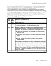
1313 FAIL The TN767E circuit pack could not deactivate a CPE loop-back jack loop
back.
1. Execute test ds1-loop location end-loopback/
span-test.
2. If the attempt to deactivate the CPE loop-back jack is not successful,
check the cabling and investigate the problem at the CPE loop-back
jack.
3. Run the test again.
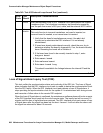
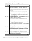
1314 FAIL The TN767E circuit pack could not deactivate a far-end CSU loop-back.
1. Execute test ds1-loop location end-loopback/
span-test.
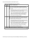
1320 FAIL A CSU module/T1 sync splitter hardware failure or an ICSU/T1 sync
splitter serial interface audit failure was detected by the TN767E DS1
circuit pack.
1. Replace the CSU module/T1 sync splitter, and then run the test again.
2. If the test continues to fail with this error code, replace the TN767E
and run the test again.
3. If the test continues to fail with this error code, the problem could be in
the I/O cable between the backplane and the CSU module/T1 sync
splitter.
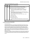
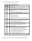
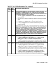
Table 344: Test #138 Loss of Signal Alarm Inquiry Test (continued)
Error
Code
Test
Result
Description / Recommendation
5 of 7