


Communication Manager Maintenance-Object Repair Procedures
2392 Maintenance Procedures for Avaya Communication Manager 3.0, Media Gateways and Servers
Aux Data 3: the 24-/32-channel option jumper setting on the circuit pack does not match
the option set on the DS1 Circuit Pack administration screen. The circuit pack must be
physically removed to see the setting of the jumper.
e. Error Type 257: associated with the Common Port Circuit Pack Maintenance test. See
XXX-BD (Common Port Circuit Pack/Media Module)
on page 2539 for details.
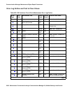
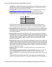
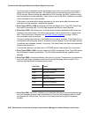
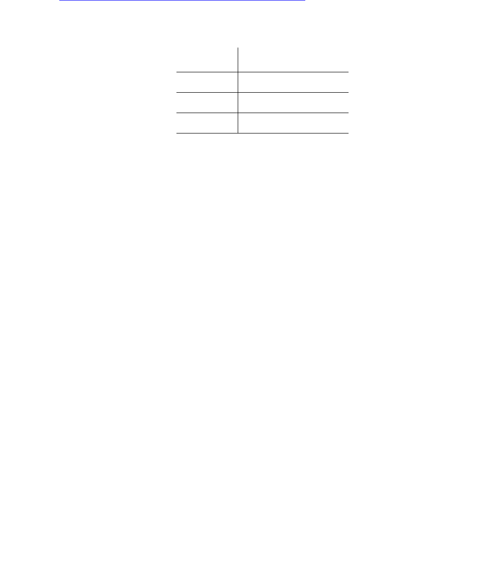
f. Error Type 513: the UDS1 Interface circuit pack has detected a transient hardware
problem. The value in the Aux Data field indicates the type of hardware problem:
If the UDS1 board detects only one of these hardware problems, then the error will
disappear when none of these faults are detected for 10 minutes. If the same Aux Data
value is logged more than once in a 24-hour period, the circuit pack should be replaced.
g. Error Type 514: LAN External RAM Error. This error occurs when there is a hardware fault
in the external RAM. The RAM is used for message buffering to and from the Packet bus.
This error should not occur frequently. If it does (10 times within 30 minutes), the circuit
pack should be replaced.
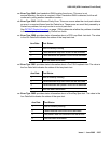
h. Error Type 769: transmit FIFO Underflow Error. This error occurs when the circuit pack
cannot find the “end of frame” bit when transmitting a frame to the Packet bus. An alarm is
raised if this error occurs three times within 10 minutes. Clear the alarm using the following
commands: busyout board location, reset board location, test board
location long, release board location. If the error recurs within 10 minutes,
replace the circuit pack.
i. Error Type 770: unable to Write LAN Translation RAM Error. This error occurs when a call
is aborted because there are no available translation RAM locations for the call connection
attempt. An alarm is raised if this error occurs two times within 10 minutes. Clear the alarm
using the following commands: busyout board location, reset board location,
test board location long, release board location. If the error recurs within 10
minutes, replace the circuit pack.
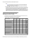
j. Error Type 1300: CSU module/T1 sync splitter missing or E1 synchronization splitter
(E1SS) missing.
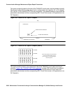
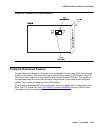
CSU module/T1 sync splitter missing: The Near-End CSU Type field on the add ds1
screen is integrated but the 120A1 CSU module or the 401A T1 sync splitter is not
physically connected (or is improperly connected) to the UDS1 board on the back of the port
carrier.
If using the 120A1 CSU module or the 401A T1 sync splitter, plug (or replug) the CSU
module/T1 sync splitter into the UDS1 circuit pack’s connector on the I/O connector panel
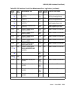
Aux Data Problem
4352 External RAM failure
4353 Internal RAM failure
4355 Internal ROM failure