


Communication Manager Maintenance-Object Repair Procedures
532 Maintenance Procedures for Avaya Communication Manager 3.0, Media Gateways and Servers
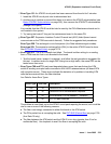
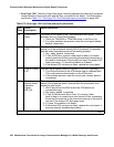
Notes:
a. Error Type 0: Run the short test sequence first. If every test passes, run the long test
sequence. Refer to each appropriate test’s description, and follow its recommended
procedures.
b. Error Type 2: The on-board DUART chip failed. This results in communication failure
between the PN’s Maintenance board and the ATM-EI board. The Maintenance board
should have a red LED lit, because the link to the ATM-EI is down in this PN.
1. Reset the board with reset board location.
2. If the board does not recover, replace the board.
c. Error Type 18: The ATM-EI circuit pack has been busied out.
1. Release the circuit pack (release board location).
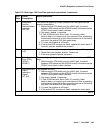
d. Error Type 23: An ATM-EI circuit pack has been administered with the add atm pnc n
command, but the circuit pack has not been inserted into the system.
1. Insert an ATM-EI circuit pack at this location.
e. Error Type 125: A wrong circuit pack is located in the slot where the ATM-EI circuit pack is
logically administered.
1. Either remove the wrong circuit pack and insert the ATM-EI circuit pack or remove the
ATM-EI administration (see Basic ATM PNC Administration
on page 528).
2. Remove the ATM-INTF administration and re-administer the slot (change circuit-pack) to
match the circuit-pack that is physically present in this slot.
3585 (u
) ATM Framer
Looparound (#1260)
MAJ ON test board location l
3586 (u
) ATM Framer
Looparound (#1260)
MAJ ON test board location l
3841 (v
)
3842
(w
)
3843 (x
) None
3999 (y
) Any None
Any (z
) 32767 None
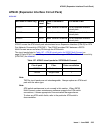
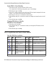
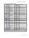
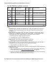
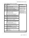
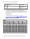
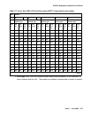
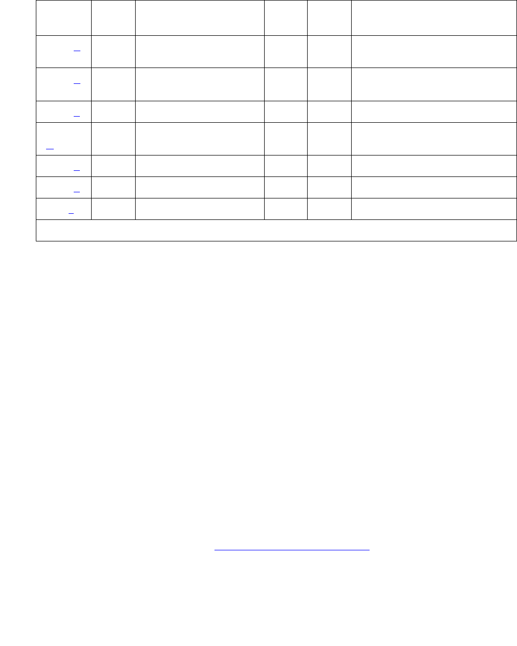
Table 169: ATM-EI Error Log Entries (continued)
Error
Type
Aux
Data
Associated Test Alarm
Level
On/Off
Board
Test to Clear Value
3 of 3