


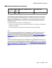
RMC-ENV (Power/Fan Sensors)
Issue 1 June 2005 1951
RMC-ENV (Power/Fan Sensors)
G600 only
The AC Power Supply (650A) for a G600 media gateway (Rack-Mounted Cabinet - RMC)
supports one alarm lead that indicates the state of both the power and fan. The cabinets use
variable-speed fans to reduce noise. The power unit contains thermal speed control. A 3-pin
connector on the variable-speed fan assembly accepts variable input power to control its fan
speed and power its alarm circuitry.
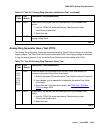
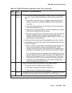
Table 717: LED and Alarm Conditions
on page 1951 shows the LED and alarm conditions.
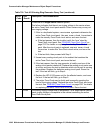
Fan Removal and Replacement
!
WARNING:
WARNING: You can remove the fan assembly while the system is running, but you must
replace the new assembly within 60 seconds to avoid a thermal overload.
1. Place the new fan assembly close to the G600.
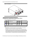
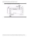
2. Loosen the thumb screws on the fan assembly, and pull it straight out (unplug it) as shown
in Figure 113: Fan Removal
on page 1952. The power for the fan automatically
disconnects when the assembly is unplugged.
3. Plug in the new fan assembly. The power for the fan automatically connects when the fan
assembly is plugged in.
4. Tighten every thumb screw on the fan assembly.
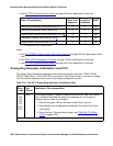
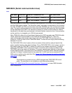
MO Name in
Alarm Log
Alarm
Level
Initial Command to Run Full Name of MO
RMC-ENV MAJ test environment Power/Fan Sensors
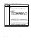
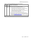
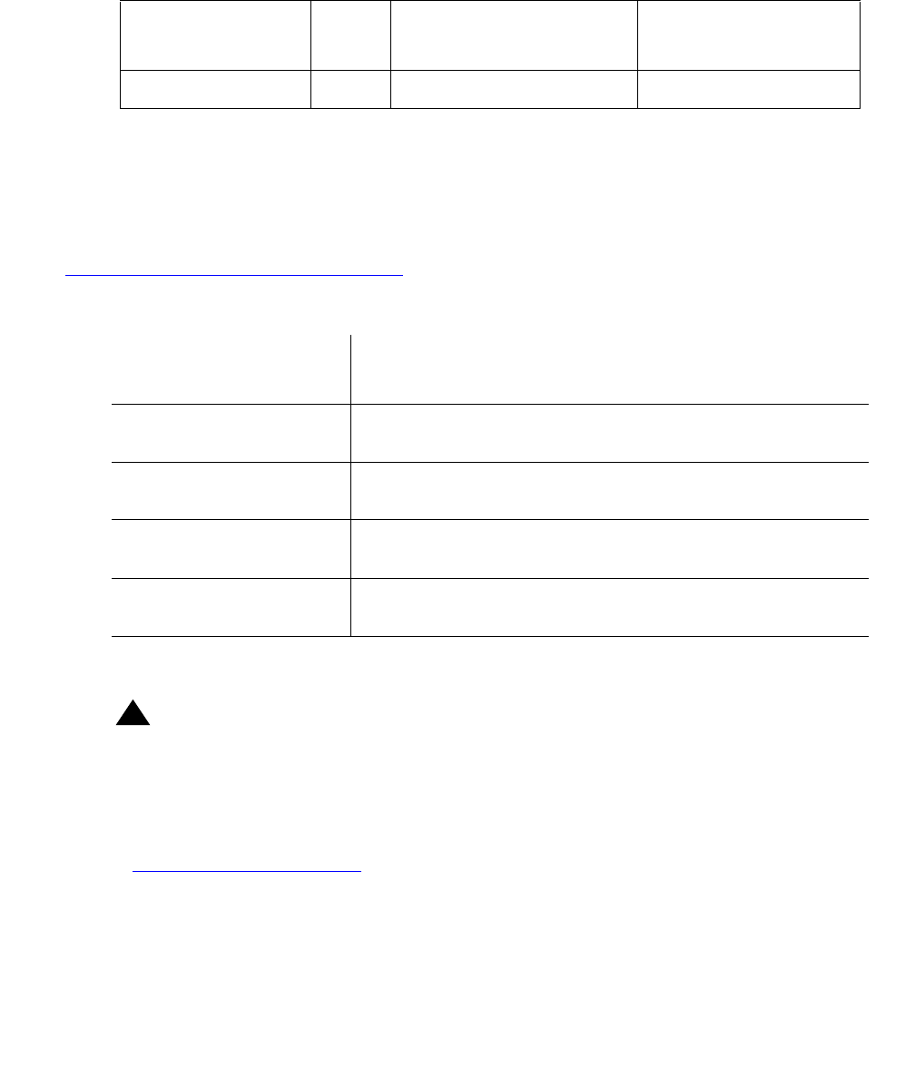
Table 717: LED and Alarm Conditions
Condition LED
Status
Alarm
State
Fan/Power Alarm
Normal Red off,
amber on
Open Normal
No input power Red off,
amber off
Closed No input power
DC output not present
(except neon)
Red on,
amber off
Closed DC output not present
(except neon)
Fan alarm Red on,
amber on
Closed Fan/Power alarm