Communication Manager Maintenance-Object Repair Procedures
1962 Maintenance Procedures for Avaya Communication Manager 3.0, Media Gateways and Servers
After cabling changes are made and verified, power must be restored to the port network.
Circuit packs in carriers that are not part of the shortened bus are not inserted. As a result,
these circuit packs are alarmed. Ignore these alarms for now. All alarms should be resolved
when the cabinet is restored to its original configuration.
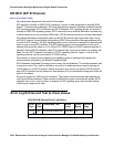
Procedure 2 is organized into two parts:
● Part 1 attempts to clear the Serial Bus fault by replacing all the bus cabling and terminators
within a port-network.
● Part 2 attempts to isolate the fault to a particular carrier by extending the Serial Bus from
the A carrier to additional carriers one at a time.
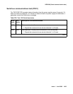
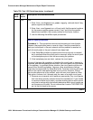
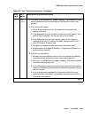
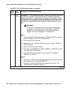
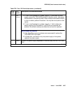
Refer to the repair procedure steps given under Serial bus communications test (#1531)
on
page 1963
Error log entries and test-to-clear values
a. Error type 257: serial bus failure. There are no power supplies detected on the serial bus.
System technician-demanded test: Descriptions and error codes
Error
Type
Aux
Data
Associated Test Alarm
Level
On/Off
Board
Test-to-clear value
257 (a
) Serial Bus
Communications (#1531)
MIN Off test environment location
Order of investigation Short test
sequence
Long test
sequence
D/ND
1
1. D = Destructive, ND = Nondestructive
Serial Bus Communications Test (#1531) X X ND


