


LEDs
258 Maintenance Procedures for Avaya Communication Manager 3.0, Media Gateways and Servers
LED alarms without Alarm Log entry
or with Error Type 1
Whenever the system or a part of the system is reset, every affected circuit pack will briefly light
their red and green LEDs as they are initialized. Upon power up of a newly installed system,
several alarm indicators may remain lit until the circuit packs are administered. These alarms
should be ignored until administration is completed.
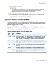
Boards with a “P” suffix have downloadable firmware. If such a board has both its green and
yellow LEDs lit simultaneously, a download may be in progress and the board will not appear to
be recognized. Use either the SAT command status firmware download or status
firmware download last to verify this condition.
G350: For G350 - WAN media modules, MM314, MM340, and MM342. If these media modules
are inserted in a slot administered for a voice media module the red LED will be lit.
After a circuit pack has been initialized, a red LED should be accompanied by an alarm in the
alarm log. A single fault can sometimes light alarm LEDs on several circuit packs, as in the
following examples.
● A TDM bus problem may cause several port circuit packs to display red LEDs.
● A Maintenance circuit pack can prevent an Expansion Interface (EI) circuit pack from
initializing.
● Extensive interactions in the Center Stage Switch (CSS) can cause multiple alarms from
single faults in DS1C, SNI and SNC circuit packs and fiber links.
● Tone-Clock problems may cause other circuit packs to report alarms.
● Mis-connected optical fiber cables may cause several circuit packs to alarm.
● Packet-bus faults can cause several port circuit packs to display red LEDs.
If a circuit pack has had at least five minutes to be initialized, and the red LED is lit without an
associated alarm in the alarm log, the circuit pack may not be in communication with the
system. This may also be the case when a circuit pack is properly administered and present in
its slot, but there is an error type 1 logged against it. To determine whether this is so, proceed as
follows:
1. Enter the list configuration board location command. If the system does not
detect the circuit pack, this command will return:
identifier not assigned or no board.
If the documentation for the associated maintenance object gives no special instructions for
this situation, go to the next step.
2. Check the hardware error log for TONE-BD or TDM-BUS errors. If the board has a “P” suffix
execute the reset board location command, otherwise execute the test tdm and
test tone-clock commands and use the appropriate maintenance procedures to
resolve any identified faults. If this does not resolve the problem, go to the next step.