


Communication Manager Maintenance-Object Repair Procedures
618 Maintenance Procedures for Avaya Communication Manager 3.0, Media Gateways and Servers
Note:
Note: TN230x circuit packs are not interchangeable.
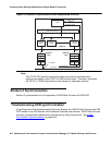
ATM Circuit Emulation Service
Under ATM Circuit Emulation Service (CES), simulate ISDN-PRI circuits by assigning ports to
signaling groups. Each signaling group represents a PRI circuit, and the ports in the group
represent the D channel and B channels of that circuit.
Virtual D channels
Non-facility associated signaling is not supported under ATM-CES, so you must reserve one
port in each signaling group for use as a D channel. Use channel 24 when emulating a T-1
ISDN facility, and channel 16 when emulating an E-1 facility. The D channel can be any
physical port from 9 to 32.
Virtual circuits
The TN230x can support a varied number of virtual circuits, depending on the switch and the
administration of the circuit pack.
Virtual trunk groups
You cannot bundle physical DS1 ISDN-PRI circuits and virtual ATM-CES circuits into the same
trunk groups. Virtual circuits can only be assigned to all-virtual, all-ATM trunk groups.
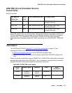
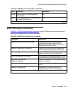
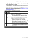
LEDs
The ATM circuit pack LEDs give you a visual indication of the condition of the TN230x circuit
pack (Table 206: ATM-TRK LED interpretation
on page 618).
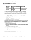
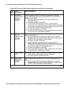
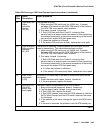
Table 206: ATM-TRK LED interpretation
LEDs Condition LED status
Red Error (alarm logged) On
Red &
Green
Booting (LEDs being tested) Blinking (on 200 ms, off 200 ms)
Green Test/maintenance in progress On
Amber Fiber Loss of Signal (LOS), LOF,
MS_RDI, MS_AIS, LCD, HP_RDI,
HP_AIS, LOP, PSC
Blinking fast (100 ms on, 100 ms off)
Amber Signal to ATM switch down Blinking slowly (500 ms on, 500 ms off)
1 of 2