


DS1-FAC (DS1 Facility)
Issue 1 June 2005 1065
Aux Data 2: indicates that the facility is detecting a yellow F5 state alarm. This error only
applies to TN1654 DS1 converter boards in 32-channel E1 operation with CRC enabled via
the fiber-link screen. The F5 fault state is defined as a fault in the user-network interface,
specifically in the direction from the user (PBX) to the network. Refer to CCITT
recommendation I.431.
The far-end facility will be in LFA state. To isolate faults for this case, follow the same repair
procedure as in Error Type #1025 (loss of frame alignment) for the other end of the DS1
facility.
i. Error Type 1537: Alarm Indication Signal (AIS), the BLUE alarm. This alarm indicates that
the far end of the facility is out of service. This means that the other end of the DS1 facility is
undergoing maintenance testing or has a LOS condition and the CSU is providing a Keep
Alive signal. If the Keep Alive signal is not supplied by the CSU, a LOS condition will exist
on the facility instead of the AIS. If a LOS condition exists on the facility, the green LED on
the TN574 DS1 converter circuit pack that is associated with the facility will be off; if an AIS
condition exists on the facility, the green LED that is associated with the facility that has the
AIS will be on. For TN1654 DS1 converter boards, the LED associated with the facility will
be lit red if either the LOS or AIS conditions exist.
To isolate faults for this case, follow the same repair procedure as in Error Type #1793 (loss
of signal) for the other end of this DS1 facility.
An RFA alarm indication (YELLOW alarm) is transmitted in response to this BLUE alarm. If
D4 framing is used, transmitted data is corrupted.
j. Error Type 1793: Loss of Signal (LOS) alarm. This alarm indicates that no signal is present
at the DS1 interface associated with the facility. On TN574 DS1 converter boards, the green
LED that is associated with the facility will be off. For TN1654 DS1 converter boards, the
LED that is associated with the facility will be lit red. If the LED behavior differs, replace the
DS1 converter circuit pack.
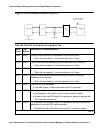
Fault isolation for this problem may be different depending on the capabilities of the CSU
device that is being used. Typically, CSUs provides an LED that is useful for fault isolation
(see Figure 52: Typical CSU Maintenance Capabilities
on page 1068). This is the “16
Zeros” LED. This LED is momentarily lit when a string of 16 consecutive zeros is detected in
the DS1 signal from the DS1 converter. Zeros on a DS1 link are represented by an absence
of a pulse. Thus, an active 16 Zeros LED indicates a LOS alarm from the DS1 converter.
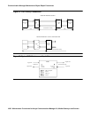
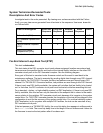
For the following repair procedure, see Figure 51: DS1 Facility Connections
on page 1068
and the diagrams in the related test descriptions.
1. If the DS1 facility side LOS indication on CSU A is off (inactive), check for a problem
between the DS1 converter A circuit pack and the CPE side of CSU A. Connectors,
cables, and the CSU may need to be replaced.
2. If the DS1 facility side LOS indication on CSU A is on (active), check for a problem
between the CSU A and the CSU B. Contact T1 Network Service to resolve the problem.
DS1 facility may be a private line or it may be connected to the Network. Network
Interface (NI) point is where the customer’s maintenance responsibility ends and the DS1
facility vendor’s maintenance responsibility begins. This point ideally is the T, R, T1, and
R1 terminals on the rear of the CSU to which the wires of the DS1 facility vendor’s DS1