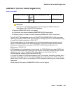
ADX16A-PT (AUDIX Analog Line/Control Link)
Issue 1 June 2005 363
ADX16A-PT (AUDIX Analog Line/Control Link)
S8700 | 8710 S8500
!
CAUTION:
CAUTION: Never do any of the following without first shutting down AUDIX. Follow the
instructions on the TN566/TN2169 faceplate:
● Remove EMBEDDED AUDIX circuit packs
● Cycle power to a carrier containing EMBEDDED AUDIX circuit packs
● Remove power to a carrier containing EMBEDDED AUDIX circuit packs
The ADX16A-PT MO represents a port on a TN566/TN2169 EMBEDDED AUDIX circuit pack
that is operating in control-link (CL) mode. For circuit-pack-level problems (ADX16A-BD or
ANL-16-BD), see XXX-BD (Common Port Circuit Pack/Media Module)
on page 2539. For
port-level problems with AUDIX operating in digital-port mode, see:
● ADX8D-PT (AUDIX Digital Port) on page 345
● ADX16D-P (16-Port AUDIX Digital Port) on page 355
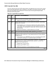
The tests described in this section apply only to switch-side maintenance that tests a circuit
pack’s components related to the TDM-bus interface. The AUDIX system has an extensive
maintenance strategy that is described in DEFINITY AUDIX System Release 3.2.4
Maintenance, 585-300-110.
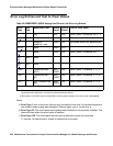
AUDIX resides on a combined pair of circuit packs: the TN566 Multifunction board (MFB) and
the TN2169 Alarm board (ALB). Because of its size this combination occupies 5 slots, but only 1
slot is functional as far as the switch is concerned. The other 4 slots are seen by the switch as
“AUDIX-reserved” slots.
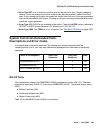
In CL mode the TN566 pack supports up to 16 voice ports. When a call to a station with an
AUDIX login is not answered, AUDIX answers the call using one of the available voice ports.
Unlike other AUDIX systems, EMBEDDED AUDIX is not an adjunct.
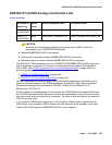
MO Name in
Alarm Log
Alarm
Level
Initial Command to Run Full Name of MO
ADXCL-PT
or ADX16A-P
MIN test port location l AUDIX Analog Line/ Control Link
ADXCL-PT
or ADX16A-P
WRN test port location sh AUDIX Analog Line/ Control Link


