


Communication Manager Maintenance-Object Repair Procedures
1064 Maintenance Procedures for Avaya Communication Manager 3.0, Media Gateways and Servers
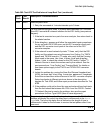
4. If Test #799 passes, run the Far-End Internal Loopback test (#797) via test
ds1-facility location long. If Test #797 passes, go to step 6. If the test fails,
then run the Near-End External Loopback test (#799) via test ds1-facility
location external-loopback at the other end of the DS1 converter complex, and
repeat steps 2 and 3 for the other endpoint.
If this is not a critical-reliability system and if there is only one DS1 facility, then Test #799
can only be executed at the end that is closer to the media server relative to the DS1
converter circuit pack at the end of the DS1 converter complex. If the test cannot be
executed for this reason, then replace the cables, connectors and the CSU at the other
end of the DS1 converter complex.
5. If the problem could not be isolated by the near-end external loop-back tests, then the
fault should be between CSU A and CSU B. Contact T1 Network Service to resolve the
problem(*).
6. If the problem still persists, check for excessive slips and synchronization problems.
Enter display errors and follow the associated repair procedures for any SYNC,
TDM-CLK, or SNC-BD errors. For TN574 boards and TN1654 boards in T1 mode, check
line equalization settings as described in the previous section, DS1 Converter-1 and DS1
Converter-2 Line Compensation on page 1058.
7. Enter display errors and follow the associated repair procedures for any EXP-INTF,
and SNI-BD errors for the Fiber Endpoints. Enter display errors and follow the
associated repair procedures for any FIBER-LK errors for this fiber link.
8. If the problem still persists, replace this DS1 converter circuit pack.
9. If the problem still persists, replace the DS1 converter circuit pack at the other end of the
DS1 converter complex.
If D4 framing mode is used, an in-band alarm signal (RFA) will be transmitted that will
corrupt the transmit data on this facility.
h. Error Type 1281:
Aux Data None: This entry in the DS1 Facility Error Log occurs only prior to Release V5.
The DS1 converter circuit pack's neighbor (the DS1 converter circuit pack at the other end
of the DS1 converter complex) is unable to frame up on the signal being sent to it by this
DS1 converter circuit pack on this DS1 facility. The far-end facility will be in LFA state. To
isolate faults for this case, follow the repair procedure for Error Type #1025 for the other end
of the DS1 facility. Note that references to the near and far ends are reversed, for example,
the neighbor is now the near end. If D4 framing is used, received data will be corrupted as
well as transmitted data.
Aux Data 1: indicates that the facility is detecting a Remote Frame Alarm (RFA), also
known as the YELLOW alarm, being sent by the remote DS1 endpoint. This Yellow alarm
corresponds to the yellow F2 state documented in CCITT Recommendation I.431. If D4
framing is used, received data will be corrupted in addition to transmitted data.