


Communication Manager Maintenance-Object Repair Procedures
1966 Maintenance Procedures for Avaya Communication Manager 3.0, Media Gateways and Servers
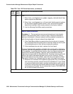
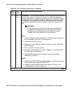
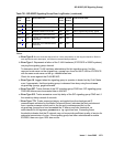
FAIL
(
cont’d)
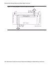
Procedure 2: - This procedure attempts to isolate the Serial Bus failure to a
particular set of carriers. Only the circuit packs in selected carriers are
checked. Procedure 2 is organized into two parts. Part 1 attempts to clear
the Serial Bus fault by replacing all the bus cabling and terminators within a
port-network. Part 2 attempts to isolate the fault to a particular carrier by
extending the Serial Bus from the A carrier to additional carriers one at a
time.
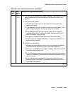
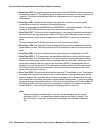
!
WARNING:
WARNING: Power must be removed from the entire port network before
any cables or terminators are removed. Failure to follow this
procedure can cause damage to circuit packs and power
supplies, and can be hazardous to the technician.
Part 1:
1. If spare TDM/LAN Cable assemblies and TDM/LAN Bus Terminators
are not available, go to Part 2 of this procedure.
2. Power down the port network.
3. Replace all of the TDM/LAN Cable Assemblies and both TDM/LAN
Bus Terminators.
4. Restore power to the port network.
5. Run list configuration power-supply C to determine if the
Serial Bus fault is still present.
6. If the Serial Bus fault is resolved, the procedure is completed.
Otherwise, go to Part 2.
Part 2:
1. Terminate the TDM/LAN Bus so that it extends only across the carrier
that contains the A carrier TN2312BP IPSI.
2. Determine if the Serial Bus fault is still present by running list
configuration power-supply C.
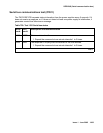
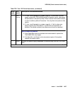
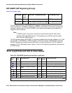
Table 720: Test 1531 Serial bus status (continued)
Error
code
Test
result
Description and recommendation
4 of 5