


EXP-INTF (Expansion Interface Circuit Pack)
Issue 1 June 2005 1183
Restoring Normal Service to the SREPN
!
WARNING:
WARNING: Every call within the SREPN is terminated when the SREPN feature is returned
to normal service.
To restore normal connections to the SREPN EI circuit pack in the S8700 Multi-Connect PN,
you must:
1. Clear every error logged against the S8700 Multi-Connect SREPN EI circuit pack by using
the suggested repair procedures outlined in this MO.
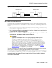
2. At the SRP flip the 3-position switch on the TN2301 to the RSTR (restore) or top position for
at least 1 second and return the switch to the AUTO, or middle position.
3. After the SREPN slide switch has been restored to the normal position, test the connectivity
to S8700 Multi-Connect EI LAPD link, by using the suggested procedures outlined in this
MO.
4. After normal service is returned to the S8300 Media Server with G700 Media Gateway
SREPN, the SRPPN will be in an alarmed state. This is normal for an SRPPN and indicates
that the:
● SRSwitch (TN2301) has disconnected it from its neighbor (EI in the SREPN)
● SRPPN is no longer in control.
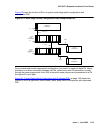
Connectivity has been reestablished between the EI in the SREPN and its counterpart EI circuit
pack in the S8700 Multi-Connect PN. The system is now in a normal S8700 Multi-Connect EI
configuration.
LEDs
SREPN Expansion Interface
The EI circuit pack has red, green, and amber LEDs. The red and green LEDs show the
standard conditions:
● Red indicates an alarm condition.
● Green indicates maintenance testing in progress.
The amber LED is used to provide useful visual status information:
● Active EI circuit packs:
- Have their amber LED on solid (for an inter-EPN EI in a direct connect system)
- Blink a pattern of 2 seconds on and 200 ms off.
● The standby PNC EI circuit packs should have their amber LEDs off.