


Communication Manager Maintenance-Object Repair Procedures
1054 Maintenance Procedures for Avaya Communication Manager 3.0, Media Gateways and Servers
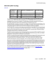
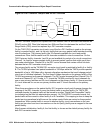
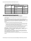
Figure 50: DS1 Converter Complex and the DS1 Facilities
The DS1 converter complex can replace fiber links between two EIs and fiber links between an
PN’s EI and an SNI. Fiber links between two SNIs and fiber links between the and the Center
Stage Switch (CSS) cannot be replaced by a DS1 converter complex.
On the TN574 DS1 converter circuit pack, one of the four DS1 facilities is used as the primary
facility (or packet facility), and it is the only facility that can carry packet traffic besides providing
circuit connections. The primary facility has 22 channels available for circuit and packet
connections. Other facilities each have 24 channels available for circuit connections. On the
TN574 primary facility, channels 1and 24 are not available for packet or for circuit connections.
Channel 1 is used for excess packets traffic to prevent packet overflow that might result from
zero code substitutions. Channel 24 is the DS1 control channel that carries control link data
between the two DS1 converter circuit packs.
The primary facility on the TN1654 DS1 converter circuit pack is restricted to facility A or facility
B. The TN1654 provides fixed packet bandwidth of 192 kbps while the TN574 provides packet
bandwidth of up to 1408 kbps with a dynamic allocation mechanism that could change packet/
circuit use of individual channels. The first three 64-kbps channels on the primary facility of the
TN1654 are reserved as the packet channels. The DS1 control channel will be Channel 24 in T1
mode and Channel 31 in E1 mode. In T1 format the TN1654 provides 24 circuit channels for
use on non-primary facilities and 20 circuit channels on the primary facility. E1 format provides
31 circuit channels for use on non-primary facilities and 27 circuit channels on the primary
facility.
When there are alarms on the packet facility, DS1 converter circuit pack firmware changes the
mapping of the DS1 channels to move the packet traffic to another facility. On TN574 DS1
converter boards, the packet traffic will be moved to another “Digital Data Compatible” facility
(as indicated on the fiber link administration screen). On TN1654 DS1 converter boards, the
packet traffic will be moved to either facility A or B if available. This mapping is done to keep the
packet service operational at all times as the system control links are carried on these packet
connections. When packet traffic is moved to another facility, circuit connections on the new
facility are torn down and circuit connections on the old (faulty) facility are re-mapped to the new
packet facility.
After firmware initialization, facility A, the first facility, is chosen as the default primary facility for
both DS1 converter boards.
Metallic or Fiber Connection
DS1CONV
DS1 Facilities
Network
EI
or
SNI
EI
DS1CONV
Metallic or Fiber Connection