


Communication Manager Maintenance-Object Repair Procedures
2348 Maintenance Procedures for Avaya Communication Manager 3.0, Media Gateways and Servers
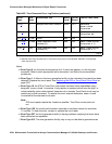
4. Interchange the IPSI or Tone-Clock circuits, using set tone-clock location. If the
command succeeds, the interchange that previously failed has been accomplished and
the problem has been satisfactorily resolved. If it fails, proceed to the next step. You may
want to proceed in any case to definitively test all relevant components.
5. Interchange the t/c selector using set expansion-interface. If errors prevent this
interchange, resolve them first.
6. Attempt again to interchange Tone-Clocks with set tone-clock location.
If the Tone-Clock interchange failed for both t/c selectors, replace the standby
Tone-Clock circuit pack which could not be interchanged into and return to this step. (See
Replacing the IPSI or Tone-Clock Circuit Pack
on page 2337.) Test the new circuit pack
as follows:
a. Execute set tone-clock location.
b. Execute set expansion-interface.
c. Execute the set tone-clock location command again.
If these commands successfully complete, the problem has been resolved.
If these commands successfully complete, the problem has been resolved.
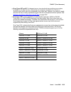
If the IPSI or Tone-Clock circuit packs successfully interchange when one EXP-INTF is
active, but not when the other one is, the t/c-selector circuit pack on the failing side is
suspect.
d. Replace the EXP-INTF board that is active when the Tone-Clock interchange fails. For
the Expansion Interface, see EXP-INTF (Expansion Interface Circuit Pack)
on
page 1176. Follow procedures in Reseating and replacing circuit packs
in
Maintenance Procedures (03-300192), and “Reliability Systems: A Maintenance Aid”
for the DUPINT circuit pack
e. Make sure the new t/c selector is active and execute set tone-clock location.
f. If both Tone-Clocks can be interchanged into, and interchanges succeed when either
t/c selector is active, the problem has been resolved.
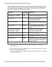
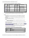
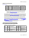
o. Error Type 3840: this error is not service-affecting and can be ignored. It indicates that the
circuit pack has received a bad control message from the switch.
p. Error Type 3848: the IPSI or Tone-Clock circuit pack had a loss of clock. If error 2305 is
also logged, see Note k.
q. Error Type 3856: the IPSI or Tone-Clock circuit pack had a loss of clock. If error 2305 is
also logged, see the note for Error Type 2305.
r. Error Type 3857 and 3858: these errors are reported by software when an uplink message
is received from the active IPSI’s Archangel firmware. Both Error Types indicate that a loss
of one or more clock signals were detected by the archangel, and subsequently restored by
changing the CLKSEL lead.