Communication Manager Maintenance-Object Repair Procedures
2270 Maintenance Procedures for Avaya Communication Manager 3.0, Media Gateways and Servers
TIE-DS1 (DS1 Tie Trunk)
S8700 | 8710 / S8500 / S8300
Note:
Note: Many trunk problems are caused by incorrect settings of parameters on the trunk
group administration form. Settings must be compatible with the local
environment and with parameter settings on the far end. Refer to Administrator
Guide for Avaya Communication Manager, 03-300509 for information on how to
administer trunks. The Application Notes section of that book shows the correct
settings for administrable timers and other parameters on a country-by-country
basis.
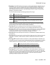
The DS1 tie trunk provides both voice and data communications between two PBX switches.
There are two types of DS1 interfaces:
● 24 DS0 channels on a 1.544-Mbps link
● 31 DS0 channels + 1 framing channel on a 2.048-Mbps link
Note:
Note: 32-channel mode is supported only on TN464 circuit packs.
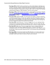
DS1 Tie Trunks are used widely in the Distributed Communications System (DCS) and Central
Attendant Service (CAS) system features. A DS1 tie trunk can also be used as an access
endpoint which is a non-signaling channel with bandwidth for voice-grade data, 56- or 64-kbps
data. DS1 tie trunk maintenance provides a strategy to maintain a DS1 tie trunk via a port on the
TN722 or TN767 DS1 Interface circuit pack, the TN464 UDS1 Interface circuit pack, or the
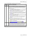
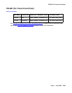
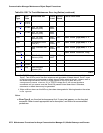
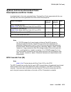
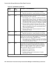
MO Name Alarm Level Initial SAT Command to Run Full Name of MO
TIE-DS1
1
1. For additional repair information, see DS1-BD (DS1 Interface Circuit Pack) on page 978 if the
tie trunk is on a TN722 or TN767 DS1 circuit pack. See UDS1-BD (UDS1 Interface Circuit
Pack) on page 2374 UDS1-BD documentation if the tie trunk is on a TN464 UDS1 circuit pack.
See MG-DS1 (DS1 Interface Media Module)
on page 1594 if the tie trunk is on an MM710 DS1
Interface Media Module.
MAJ
2
2. A MAJOR alarm on a trunk indicates that alarms on these trunks are not downgraded by set
options and that at least 75% of the trunks in this trunk group are alarmed.
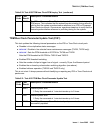
test trunk grp#/mem# long
3
3. For TN767B vintage 8 or 9 circuit packs, a failure of Test #136 causes a subsequent failure of
Test #7. Test #136 is part of the short sequence and generates off-board alarms. Test #7 is
part of the long sequence and generates on-board alarms. Before entering busyout, release,
reset or test board long commands, check the vintage number of the circuit pack with list
configuration board location. If it is TN767B vintage 8 or 9, do not use the above
commands until you ensure that Test #136 passes via test board short. Otherwise, extraneous
on-board alarms may be generated.
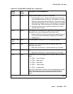
DS1 Tie Trunk
TIE-DS1 MIN test trunk grp#/mem# long
3
DS1 Tie Trunk
TIE-DS1 WRN test trunk grp#/mem# DS1 Tie Trunk


