


ATM-EI (Expansion Interface Circuit Pack)
Issue 1 June 2005 539
19 Multiplexer
Section
Remote Defect
Indicator:
MS_RDI
The far end is detecting a major problem with the signal that this
board is transmitting.
1. Make sure the ATM switch port (or a MUX port, if present
between ATM switch and the ATM-EI board) is the same as the
ATM-EI circuit pack’s cable interface.
2. Run test board location.
3. If Test #1259 fails with Error Code 19, connect a fiber
back-to-back in a looped mode (one strand of fiber connecting
the transmit transceiver to the receive transceiver of the board)
and see if the amber LED flash goes away.
4. If it does the problem is off-board.
5. If the amber LED continues to flash, replace the circuit pack; if
the error persists, escalate the problem.
20 Loss of pointer:
LOP
ATM framer chip is unable to access the payload part of the signal.
1. Reset the board (reset board location).
2. If the error persists replace the board.
21 Path Signal
Error (PSL)
(STM1/
SONET)
The incoming signal payload is not set up for transmission of ATM
data.
1. Make sure the ATM switch port (or a MUX port, if present
between ATM switch and the ATM-EI board) is the same as the
ATM-EI circuit pack’s cable interface.
22 High-level Path
Alarm
Indication
Signal:
HP_AIS
The payload is invalid.
1. Make sure the ATM switch port (or a MUX port, if present
between ATM switch and the ATM-EI board) is the same as the
ATM-EI circuit pack’s cable interface.
2. Run test board location.
3. If Test #1259 fails with Error Code 22, connect a fiber
back-to-back in a looped mode (one strand of fiber connecting
the transmit transceiver to the receive transceiver of the board)
and see if the amber LED flash goes away.
4. If it does the problem is off-board.
5. If the amber LED continues to flash, replace the circuit pack.
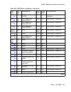
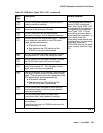
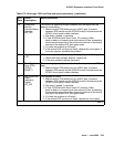
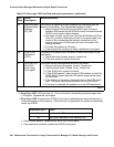
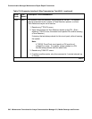
Table 172: Error type 1281 Aux Data and repair procedures (continued)
Aux
Data
Alarm
Description
Repair procedure
2 of 3