


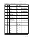
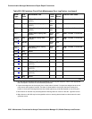

UDS1-BD (UDS1 Interface Circuit Pack)
Issue 1 June 2005 2393
on back of the carrier. Otherwise, set the Near-End CSU Type field using the change ds1
screen to other.
If this error remains after plugging the CSU module/T1 sync splitter into the board’s
connector, there could be a problem with the I/O connector panel.
E1 synchronization splitter missing: The E1 Sync-Splitter field on the add ds1 screen
is y, but the 402A or 403A E1 synchronization splitter is not physically connected (or is
improperly connected) to the UDS1 board on the back of the port carrier.
If using the 402A or 403A E1 synchronization splitter, plug (or replug) the E1SS into the
UDS1 circuit pack’s connector on the I/O connector panel on back of the carrier. Otherwise,
set the E1 Sync-Splitter field using the change ds1 screen to n.
If this error remains after plugging the E1SS into the board’s connector, there could be a
problem with the I/O connector panel.
k. Error Type 1301: CSU module/T1 sync splitter not expected or E1 synchronization splitter
not expected.
CSU Module/T1 Sync Splitter not expected: The 120A1 CSU module or the 401A T1
sync splitter is physically connected to the UDS1 board on the back of the port carrier, but
the Near-End CSU Type field on the add ds1 screen is not set to integrated.
If the 120A1 CSU module or the 401A T1 sync splitter is to be used, use change ds1 to
set the Near-End CSU Type field to integrated. Otherwise, physically remove the 120A1
CSU module or the 401A T1 sync splitter from the back of the port carrier.
E1 synchronization splitter not expected: The 402A or 403A E1 synchronization splitter
is physically connected to the UDS1 board on the back of the port carrier, but the E1
Sync-Splitter field on the add ds1 screen is not set to y.
If the 402A or 403A E1 synchronization splitter is to be used, use change ds1 to set the
E1 Sync-Splitter field to y. Otherwise, physically remove the 402A or 403A E1
synchronization splitter from the back of the port carrier.
l. Error Type 1302: DS1 configuration error. Attempting to use the 120A1 CSU module with a
UDS1 circuit pack that is configured for 32-channel (2.048-Mbps) operation. The CSU
module only works with a DS1 board configured for 24-channel (1.544-Mbps) operation in
the United States of America.
m. Error Type 1303: DS1 circuit pack suffix incorrect for CSU module/T1 sync splitter or for E1
synchronization splitter.
DS1 circuit pack suffix incorrect for CSU module/T1 sync splitter: The Near-End CSU
Type field on the
add ds1 screen is set to integrated but the DS1 circuit pack is not a
TN464F or higher suffix UDS1 board.
If the 120A1 CSU module or the 401A T1 sync splitter is to be used, remove the circuit pack
and replace it with a TN464F or higher suffix board. Otherwise, use change ds1 to set the
Near-End CSU Type field to other.