Communication Manager Maintenance-Object Repair Procedures
1520 Maintenance Procedures for Avaya Communication Manager 3.0, Media Gateways and Servers
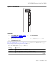
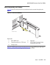
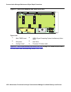
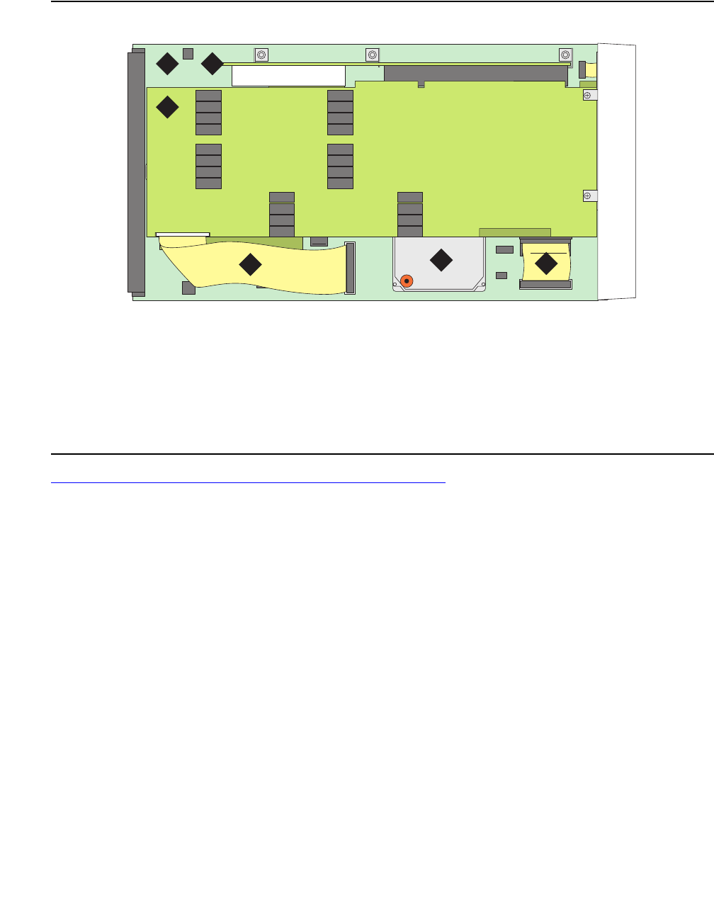
Figure 87: TN802 board assembly and cables (side view)
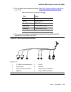
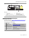
Figure 88: TN802 board assembly and cables (end view) on page 1521 shows the end view of
the three boards and interconnecting cables on the TN802.
Figure notes:
1.
Main TN802 board
4.
SCSA (Signal Computing System Architecture) ribbon
cable
2.
Side plane
5.
Hard drive
3.
Analogic board
6.
Processor I/O ribbon cable
cddfmap2 KLC 040699
1 2
3
4
5
6


