


TDM-CLK (TDM Bus Clock)
Issue 1 June 2005 2255
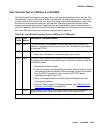
e. Error Type 257: the Tone-Clock circuit pack in PN 1 is not a TN780 although Stratum-3
synchronization is administered. Either:
1. If a Stratum-3 clock is being used, replace this Tone-Clock with a TN780.
2. If not, change synchronization administration to Stratum 4.
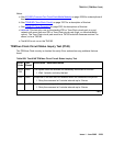
f. Error Type 513: the tone-clock has reported an out-of-lock condition. A aux value of 1
indicates this error is an out-of-lock with the primary reference. An Aux Data value of 2
indicates that this error is an out-of-lock with the secondary reference. It could not lock onto
the frequency of that synchronization reference. This will lead to a change in the
synchronization reference if the condition continues.
S8700 | 8710 / S8500
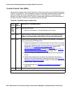
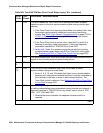
g. Error Type 769: The IPSI’s Tone-Clock circuit or Tone-Clock circuit pack might be defective,
however it may be a software failure that can be corrected by testing.
1. Check to see if the board is duplicated (list cabinet and status port-network)
on the affected port network.
2. If the board is not duplicated, use test tone-clock location long to resolve the
errors. The long test resets the board and is required to reload on-board RAM associated
with the TN2182’s DSPs. The effect is that tone detectors are taken out of service
momentarily and tones are removed from the TDM bus for about 10 seconds, meaning
that no dial tone or touch tones are available during this interval. This will probably not
affect calls in progress, but could cause a call origination to abort or a user not to get dial
tone when going off hook.
3. If every test passes and the alarm does not resolve, retest with test tone-clock
location long clear.
4. If the test passes, terminate the repair process. If the test fails, replace the circuit pack at
the customer’s convenience.
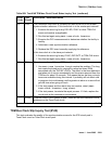
5. If this error was logged against the standby Tone-Clock, and if the Aux Data value was
18369, SYNC (Synchronization) maintenance acts on this error. No corrective action is
required. For any other Aux Data, go to the next step.
6. If the board is duplicated, switch to the standby side (set tone-clock).
7. Test the alarmed board (test tone-clock location long). This resets the board
and is required to reload on-board RAM associated with the TN2182’s DSPs.
8. If every test passes and the alarm does not resolve, retest (test tone-clock
location long clear).
9. If the test passes, terminate the repair process. If the test fails, replace the circuit pack at
the customer’s convenience.