


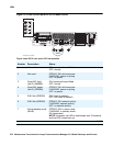

LEDs
274 Maintenance Procedures for Avaya Communication Manager 3.0, Media Gateways and Servers
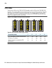
LED indicators of serial bus commands to the power supply
Operation of the 655A power supply LED indicators for visual indication of serial bus commands
to the power supply for power supply shutdown and ringing shutdown are described below.
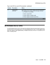
Power supply shutdown
The 655A power supply can be commanded off for a period selectable from 1 to 255 seconds.
The intent is to allow a hard reset to the G650 chassis remotely. The yellow LED indicating
correct operation of the 655A power supply is on for normal power supply operation. When the
power supply is commanded off, the yellow LED blinks at a rate of 1 second on and 100ms off,
indicating that the power supply is operational but commanded off by the serial bus.
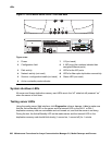
Ringing shutdown
The left hand power supply in the G650 cabinet is the master ringer. If the master ringer fails,
ringing is transferred to the redundant power supply, if present, and the red LED on the left hand
power supply turns on and the yellow LED turns off, indicating failure of the power supply.
The serial bus can command the ringer off for a period of 1 to 255 seconds. The purpose of this
command is to verify redundant ringer operation through the serial bus, remotely from the G650
chassis. The red LED blinks at a rate of 1 second on and 100ms off, indicating that the power
supply is operational but commanded off by the serial bus.
A second command relating to ringer operation is the to command the master ringer off, which
shuts down the master ringer and transfers control to the redundant power supply. This
command is used to permanently transfer ring voltage to the redundant power supply through
the serial bus, in order to resolve a problem with the master ringer. The red LED blinks at a rate
of 1 second on and 100ms off, indicating that the power supply is operational but commanded
off by the serial bus.
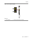
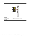
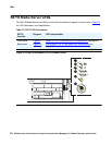
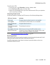
Duplication memory card LEDs
The Duplication memory card has LEDs that indicate active/standby, fiber link integrity/activity
states. The LED functions are:
● Link Active -- Green when light signal is sensed on the fiber.
● Link Sync -- Green when characters are received.
● Trans Mode -- Green when transmission is enabled.
● Receive Mode -- Green when reception is enabled.