


Communication Manager Maintenance-Object Repair Procedures
564 Maintenance Procedures for Avaya Communication Manager 3.0, Media Gateways and Servers
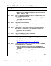
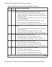
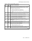
2 FAIL The test tone was transmitted and detected correctly, but the correct data
packet was not detected by the Packet Interface circuit pack.
1. Test the Packet Interface circuit pack to verify that it is functioning
properly. If any tests fail, investigate those tests and repair the Packet
Interface circuit pack.
2. If the Packet Interface circuit pack is OK, resolve any DS1C-BD alarms
or errors (if so equipped).
3. Test the ATM-EI circuit pack (test board location long).
4. If this test continues to fail, replace the ATM-EI board.
5. Test the new ATM-EI circuit pack (test board location long).
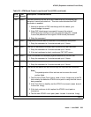
3 FAIL The test tone was transmitted correctly, but the returned tone was
distorted.
1. If the Tone-Clock is healthy, test the ATM-EI circuit pack (test board
location long).
2. If this test continues to fail, replace the ATM-EI circuit pack.
3. Test the new ATM-EI circuit pack (test board location long).
4 FAIL Unable to create loop for TDM path for this test.
1. Retry the command at 1-minute intervals up to 3 times.
2. If this test continues to fail, replace the ATM-EI circuit pack.
3. Test the new ATM-EI circuit pack (test board location long).
5 FAIL Unable to create loop for packet path for this test.
1. Retry the command at 1-minute intervals up to 3 times.
2. If this test continues to fail, replace the ATM-EI circuit pack.
3. Test the new ATM-EI circuit pack (test board location long).
6 FAIL A previously-established loop around was not released.
1. Enter reset board location.
2. Retry the command at 1-minute intervals up to 3 times.
3. If this test continues to fail, replace the ATM-EI circuit pack.
4. Test the new ATM-EI circuit pack (test board location long).
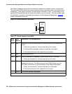
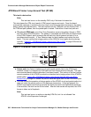
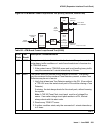
Table 181: ATM Board Framer Loop-Around Test (#1260) (continued)
Error
Code
Test
Result
Description / Recommendation
4 of 5