


Communication Manager Maintenance-Object Repair Procedures
1658 Maintenance Procedures for Avaya Communication Manager 3.0, Media Gateways and Servers
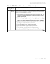
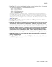
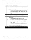
Notes:
a. Error Type 0: run the short test sequence first. If every test passes, run the long test
sequence. Refer to each test’s description, and follow its procedures.
b. Error Type 1: the circuit pack stopped functioning or it was physically removed from the
system. The alarm logs approximately 11 minutes after the circuit pack has been removed
and/or the SAKI Sanity test (#53) fails.
If the circuit pack is in the system and the red LED is on, follow the instructions for a red
alarm in Circuit pack LEDs
on page 257.
c. Error Type 18: the circuit pack was busied out using busyout board location.
d. Error Type 217: there are more than four MMI circuit packs in the system. Remove the
circuit pack that generated the error in the error log by locating the slot indicated by the
error.
e. Error Type 257: there are transient communication problems between the switch and this
circuit pack. Execute test board location and see the repair procedures for the
Control Channel Loop-around test (#52) in XXX-BD (Common Port Circuit Pack/Media
Module) on page 2539.
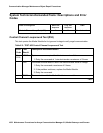
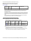
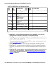
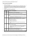
257 (e
) 65535 Control Channel
Loop test (#52)
MIN ON test board location r 3
513 (f
) 4352
to 4357
Uplink error from
circuit pack
769 (g
)Any MMI
Synchronization
Status (#1123)
1281 (h
) Any Circuit Pack
Restart test
(#594)
MAJ ON
1538 (i
) Any Software detected
error
MIN ON
1793 (j
) Any TSI XTalk (#6) MIN ON test board location l r 3
2049 (k
) Any TSI Loop (#1108) MAJ ON test board location l r 3
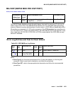
Table 613: MMI-BD Error Log Entries (continued)
Error
Type
Aux
Data
Associated Test Alarm
Level
On/Off
Board
Test to Clear Value
2 of 2